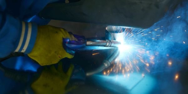
Metal inert gas (MIG) welding is gas metal arc welding (GMAW): an arc burns between a continuously fed bare wire and the workpiece, the wire melts to become the filler, and gas from a cylinder shields the pool from air. The power source is constant-voltage DC with the wire positive (DCEP), so the welder only has to guide the gun while the machine keeps the arc length steady.
For the tungsten-electrode process see TIG welding, and for flux-coated rods see stick welding.
MIG, MAG and GMAW: what the names mean
MIG stands for metal inert gas. Strictly, the name only applies when the shielding gas is inert, meaning argon, helium or a mix of the two. That is the case for aluminium, copper and most non-ferrous work.
When the gas is CO2 or an argon-CO2 or argon-oxygen mix, the process is MAG, metal active gas welding. Almost all carbon steel “MIG” welding in Indian fabrication shops is therefore MAG. ISO 4063 gives them separate process numbers: 131 for MIG and 135 for MAG with solid wire.
GMAW, the American Welding Society term, covers both.
Working principle of metal inert gas welding
- Wire feed. Drive rolls push wire from a spool through the cable liner to the gun, typically at 2 to 15 m/min.
- Current pickup. A copper contact tip passes current into the wire about 10 to 20 mm before the arc.
- Arc. The arc melts wire tip and plate; drops cross into the pool.
- Shielding. Gas leaves the nozzle at roughly 12 to 18 L/min and keeps air off the pool.
Why constant voltage? The arc regulates itself. Move the gun closer and the arc shortens, current jumps and the wire burns off faster until the arc length recovers; pull away and the reverse happens.
Why DCEP? Electrode positive gives a stable arc, good penetration and clean drop transfer with solid wire. Some self-shielded wires run DCEN; see flux-cored welding.
Metal inert gas welding machine: main parts
| Part | What it does | What to check |
|---|---|---|
| Power source | Constant-voltage DC output; transformer-rectifier or inverter | Rated current at its duty cycle; inductance control helps short-circuit work |
| Wire feeder with drive rolls | Pushes wire at a set speed | Groove matched to wire: V for solid steel, U for aluminium, knurled for flux-cored |
| Torch (gun) with contact tip | Carries wire, current and gas; trigger starts all three | Tip bore sized to the wire (a 1.0 mm tip for 1.0 mm wire); PTFE liner for aluminium |
| Gas cylinder, regulator and flowmeter | Supplies shielding gas at a set flow | Flow in L/min, no hose leaks |
| Earth (work return) clamp | Completes the circuit | On clean bare metal close to the joint |
The standard steel wire is ER70S-6 to AWS A5.18: ER is electrode or rod, 70 is 70,000 psi (about 480 MPa) minimum tensile strength of the weld metal, S is solid wire, and 6 is the grade with the highest manganese and silicon, which deoxidise the pool and tolerate light mill scale. Common diameters are 0.8, 1.0 and 1.2 mm.
Metal transfer modes
How molten wire crosses the arc depends on current, voltage and gas. Figures are typical for 1.0 mm carbon steel wire.
| Mode | How metal transfers | Typical current / voltage (1.0 mm wire) | Gas | Positions and use |
|---|---|---|---|---|
| Short-circuit (dip) | Wire touches the pool, shorts, and a drop pinches off, around 20 to 200 times a second | 60 to 160 A, 15 to 21 V | CO2 or Ar + 15 to 25% CO2 | All positions; sheet from about 1 mm, root runs, poor fit-up |
| Globular | Large irregular drops, bigger than the wire, fall under gravity | About 160 to 200 A, 22 to 26 V | Mainly 100% CO2 | Flat and horizontal only; heavy spatter, usually avoided |
| Spray | A fine stream of drops smaller than the wire, no short circuits | Above the transition current, roughly 190 to 200 A, up to about 280 A; 26 to 32 V | Argon-rich, at least about 80% Ar | Flat and horizontal fillet; thick plate, deep penetration, almost no spatter |
| Pulsed spray | Current pulses above the transition level release one drop per pulse, then drops to a low background | Peak above transition, average 80 to 200 A | Argon-rich | All positions; stainless, aluminium, thinner sections with spray quality |
Pure CO2 will not give true spray at any current.
Shielding gas by metal
| Metal | Common gas | Process name |
|---|---|---|
| Carbon steel | 100% CO2 (cheapest, deep, more spatter); Ar + 15 to 25% CO2 (smoother, general purpose); Ar + 8 to 10% CO2 for spray | MAG |
| Stainless steel | Ar + 2% CO2 or Ar + 1 to 2% O2; helium-argon-CO2 tri-mix for short-circuit | MAG (small active addition) |
| Aluminium | Pure argon; argon-helium for thick sections | MIG |
| Copper and nickel alloys | Argon or argon-helium | MIG |
Never use CO2 on aluminium: the oxygen it releases makes a sooty, porous mess.
Settings: wire feed speed and voltage
- Wire feed speed sets the current. Feed more wire and the machine must supply more current to melt it.
- Voltage sets the arc length. Higher voltage means a longer, wider arc and a flatter bead. Too low and the wire stubs into the plate; too high and the arc gets long, spattery and loses gas cover.
- Stickout matters too. Longer wire stickout preheats the wire and lowers the current at the same feed speed. Keep about 10 to 15 mm for short-circuit and 15 to 25 mm for spray.
Set feed speed for the thickness first, then trim voltage until a short-circuit arc gives a steady crackle.
Worked example: heat input
Heat input controls cooling rate, and procedures often cap it. EN 1011-1 and ISO/TR 17671-1 give:
HI = k × V × I × 60 / (1000 × travel speed in mm/min) kJ/mm
where k is the thermal efficiency factor, 0.8 for MIG/MAG (the same standard gives 1.0 for submerged arc and 0.6 for TIG).
Short-circuit fillet: 140 A, 19 V, 300 mm/min.
Arc energy = 19 × 140 × 60 / (1000 × 300) = 159,600 / 300,000 = 0.53 kJ/mm.
Heat input = 0.8 × 0.53 = 0.43 kJ/mm.
Spray pass on thick plate: 250 A, 28 V, 400 mm/min.
Arc energy = 28 × 250 × 60 / 400,000 = 1.05 kJ/mm, so heat input = 0.8 × 1.05 = 0.84 kJ/mm, about twice the short-circuit figure.
Deposition works the same way. A 1.0 mm wire has a cross-section of 0.785 mm2. At 6 m/min that is 4,712 mm3 of steel a minute, and at 7.85 g/cm3 about 37 g/min, or roughly 2.2 kg/h of arc-on time before spatter losses.

Common MIG welding defects and fixes
| Defect | Usual cause | Fix |
|---|---|---|
| Porosity | Gas cover lost: draught, empty cylinder, spatter-clogged nozzle, leaking hose, flow so high it pulls in air; or oil and paint on the plate | Screen the joint, check flow, clean the nozzle, degrease |
| Burn-through | Too much current or voltage for sheet, travel too slow, gap too wide | Lower feed speed and voltage, travel faster, stitch weld |
| Lack of fusion | Short-circuit transfer on thick plate: the cool arc lays metal on top of unmelted steel (“cold lap”) | Use spray or pulsed on thick sections, aim at the joint face, keep the arc on the pool’s leading edge |
| Spatter | Voltage too low or too high for the feed speed, pure CO2, wrong polarity, long stickout | Retune voltage, use Ar-CO2, confirm DCEP |
MIG vs TIG vs stick
| Point | MIG/MAG | TIG | Stick |
|---|---|---|---|
| Electrode | Consumable wire | Tungsten, not consumed | Consumable coated rod |
| Speed | Fastest; 2 to 5 kg/h | Slowest | Medium |
| Best for | Production and sheet work, automation | Thin, visible, stainless and aluminium work | Site work and repairs |
The TIG page has the full side-by-side on deposition, thickness and skill.
Safety
- Arc radiation. Use a helmet of shade 10 to 13 depending on current and cover all skin; spray transfer burns bare skin within minutes.
- Fume. IARC classifies welding fume as carcinogenic (Group 1). Use extraction, especially on galvanised steel.
- Shielding gas. Argon and CO2 are heavier than air and silently displace oxygen in tanks and pits.
- Cylinders. Chain upright and never strike an arc on one. The wire is live whenever the trigger is pressed.
References
- AWS A5.18/A5.18M, Specification for Carbon Steel Electrodes and Rods for Gas Shielded Arc Welding.
- EN 1011-1 and ISO/TR 17671-1, Recommendations for welding of metallic materials, general guidance for arc welding (heat input and thermal efficiency factors).
- ISO 4063, Welding and allied processes, nomenclature of processes and reference numbers.
- American Welding Society, gas metal arc welding definitions and classifications.
FAQs
What is metal inert gas welding?
Metal inert gas (MIG) welding, formally gas metal arc welding (GMAW), joins metal with an arc between a continuously fed consumable wire and the workpiece under a shielding gas. The wire is both electrode and filler, and the machine is constant-voltage DC with the wire positive (DCEP).
What is the difference between MIG and MAG welding?
The gas. MIG uses an inert gas such as argon or helium, as on aluminium and copper. MAG uses an active gas, CO2 or argon mixed with CO2 or oxygen, as on carbon and stainless steel. The machine and wire feed are the same; ISO 4063 numbers them 131 and 135.
Does wire feed speed or voltage control the current in MIG?
Wire feed speed controls the current, because the machine supplies whatever current melts the wire at that rate. Voltage controls arc length and bead width, and a longer stickout lowers current at the same feed speed.
What wire is used for MIG welding mild steel?
ER70S-6 to AWS A5.18 is the usual choice: a solid wire giving at least 70,000 psi (about 480 MPa) tensile strength, with extra manganese and silicon to deoxidise the pool. Diameters of 0.8 mm for sheet and 1.0 to 1.2 mm for general fabrication are most common.