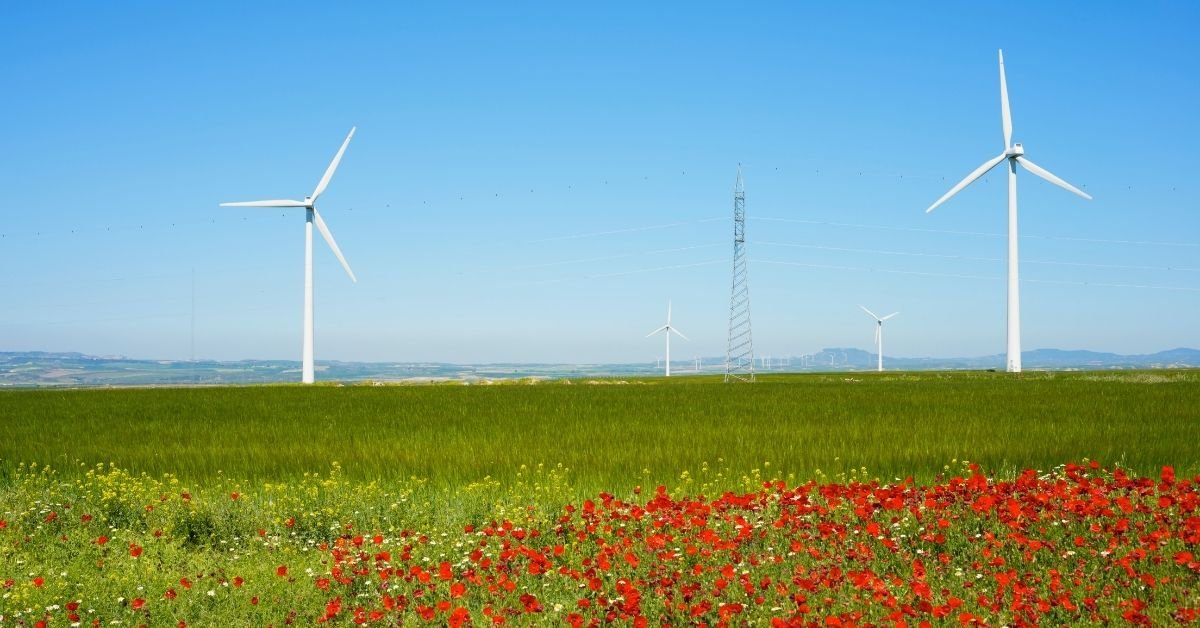
A wind turbine has four main groups of components: the rotor (blades, hub and pitch system), the nacelle with its drivetrain (main shaft, gearbox or direct drive, generator, brake and controls), the yaw system that turns the nacelle into the wind, and the tower and foundation that hold it all up. The blades turn wind into slow, high-torque rotation, the drivetrain turns that into electricity at grid frequency, and the controls keep the machine facing the wind and within safe speed.
This page is about the hardware. Why a blade produces lift, and what angle of attack and tip speed ratio mean, is covered in aerodynamic forces on wind turbine blades. For horizontal vs vertical axis designs, see design considerations of horizontal and vertical axis wind machines. Everything here describes the common three-blade, horizontal axis turbine.
How a wind turbine works
Wind flowing over the blades produces lift, which turns the rotor at roughly 10 to 20 rpm on a large machine. In a geared turbine, a gearbox raises that speed to about 1,000 to 1,800 rpm for a conventional generator; in a direct-drive turbine, a large multi-pole generator runs at rotor speed. Power electronics match the output to the grid (50 Hz in India), and a transformer steps up the voltage. The controller yaws the nacelle to face the wind and pitches the blades to limit power in strong wind or to stop the rotor.
Wind turbine components: parts table
| Component | Function | Typical construction |
|---|---|---|
| Blades | Convert wind energy into rotation using lift | Glass-fibre reinforced epoxy; carbon-fibre spar caps on long blades |
| Hub | Holds the blades and passes their torque to the main shaft | Cast iron casting |
| Pitch system | Rotates each blade about its long axis to control power and stop the rotor | Electric or hydraulic drives with backup energy store |
| Nacelle | Encloses and supports the drivetrain and controls | Steel or cast bedplate, glass-fibre cover |
| Main shaft and bearings | Carry rotor weight and thrust; transmit torque | Forged steel shaft on large roller bearings |
| Gearbox | Raises speed from about 10-20 rpm to about 1,000-1,800 rpm | Planetary and parallel-shaft stages |
| Generator | Converts mechanical power to electrical power | DFIG, permanent magnet synchronous, or induction |
| Power converter | Matches variable-speed output to grid voltage and frequency | IGBT back-to-back converter |
| Brake | Holds the rotor for maintenance; emergency backup | Hydraulic disc brake on the high-speed shaft |
| Yaw system | Turns the nacelle to face the wind | Slewing ring bearing, yaw drives, yaw brakes |
| Anemometer, vane, controller | Measure wind; start, stop, yaw, pitch and protect the turbine | Cup or ultrasonic sensors, PLC-based controller |
| Tower | Lifts the rotor into faster, steadier wind | Tubular steel, lattice, concrete or hybrid |
| Foundation | Resists the overturning moment and carries the weight | Reinforced concrete raft (onshore); monopile or jacket (offshore) |
| Transformer | Steps up generator voltage (often 690 V) to the collection voltage | Oil-filled or dry-type step-up transformer |
The rotor: blades, hub and pitch system
Rotor blades
The blades capture the energy. Most large turbines use three, which balances efficiency, smooth loading and cost. They are built from glass-fibre reinforced epoxy or polyester around a load-carrying spar, with carbon fibre in the spar caps of long blades to keep them stiff without adding much weight. Blade length matters more than anything else, because captured power depends on swept area, which rises with the square of the radius. Blades also carry lightning receptors, since they are the tallest point on the site. Why they are twisted and tapered is explained in the blade aerodynamics article.
Hub
The hub is a heavy casting that joins the blades to the main shaft. Each blade bolts to a pitch bearing on the hub so it can rotate about its own axis. A streamlined cover, the spinner or nose cone, encloses it.
Pitch system
Below rated wind speed, the pitch system holds the blades at the angle that captures the most energy. Above it, the controller pitches them to spill the excess, so the turbine holds rated power instead of overloading. Turning the blades edge-on to the wind, called feathering (about 90 degrees), stops the rotor, and this aerodynamic brake is the main way a modern turbine stops. Each blade has its own backup batteries or hydraulic accumulators so it can still feather if grid power is lost. Small and older turbines often use fixed blades and rely on stall instead.
The nacelle and drivetrain
Nacelle
The nacelle is the housing on top of the tower. Its bedplate carries the main bearing, gearbox, generator and brake and passes their loads to the yaw bearing. It also holds the cooling system, hydraulic unit, controller cabinet and usually a service crane.
Main shaft and main bearing
The low-speed main shaft carries the rotor’s weight and thrust and transmits a very large torque. Since power = torque × angular speed, 1.5 MW at 12 rpm (1.257 rad/s) means a torque of about 1.2 MN·m. The shaft runs in one or two large rolling bearings, commonly spherical or tapered roller types.
Gearbox vs direct drive
A 4-pole generator on a 50 Hz grid has a synchronous speed of 1,500 rpm. With the rotor at 12 rpm, the gearbox needs a ratio of about 1,500 / 12 = 125, usually done as a planetary stage followed by parallel-shaft helical gears. Gearboxes let the turbine use a small, cheap, high-speed generator, but they need oil and cooling, and gearbox bearing failures have historically caused long downtime.
Direct-drive turbines remove the gearbox. The generator runs at rotor speed, so it needs many poles and a diameter of several metres. There are fewer moving parts and less maintenance, at the cost of a heavier, costlier generator. Medium-speed designs sit in between, with a one- or two-stage gearbox.
Generator
- Doubly fed induction generator (DFIG): a wound-rotor induction machine used with a gearbox. The stator connects directly to the grid and the rotor connects through a converter that handles only a fraction (roughly a quarter to a third) of rated power, allowing variable speed over a limited range with a smaller converter.
- Permanent magnet synchronous generator (PMSG): rare-earth magnets on the rotor, no excitation current, efficient at low speed. The usual choice for direct-drive and medium-speed turbines, connected through a full-power converter that allows wide speed variation.
- Squirrel cage induction generator: used on older fixed-speed turbines connected straight to the grid. Simple and rugged, but it captures less energy and passes gusts straight into the drivetrain.
Brake
The main braking is aerodynamic, by feathering. A hydraulic disc brake, usually on the high-speed shaft where torque is smallest, holds the rotor still for maintenance and backs up the pitch system in an emergency. A rotor lock pin is inserted before anyone works in the hub.
Yaw system
The nacelle sits on a large slewing ring (yaw bearing) at the tower top. When the wind vane reports a lasting direction error, several electric yaw drives, each a motor and gearbox driving a pinion on the ring gear, turn the nacelle slowly, and yaw brakes then clamp it. The controller also unwinds the nacelle from time to time so the power cables hanging down the tower do not twist too far. Small turbines often use a simple tail vane instead.
Sensors, controller and transformer
An anemometer and wind vane on the nacelle roof feed the controller. It starts the turbine at the cut-in speed (typically around 3 m/s), holds rated output above the rated speed (often around 11 to 13 m/s), and shuts down at the cut-out speed (typically around 25 m/s). Exact values come from the maker’s power curve. It also watches vibration, temperatures and grid faults and reports to the wind farm’s SCADA system. The generator’s low-voltage output (690 V is common) goes to a step-up transformer that raises it to the collection voltage, commonly 33 kV on Indian wind farms.
Tower and foundation
Wind is faster and steadier higher up, and power rises with the cube of wind speed, so taller towers pay off at many sites; hub heights of 100 m or more are now common on new onshore turbines. Tubular steel towers of bolted conical sections are the standard. Lattice towers use less steel and were widely used on earlier Indian wind farms. Concrete or hybrid towers are used for very tall towers, where steel sections become too wide to move by road.
The foundation must resist the overturning moment of the rotor thrust acting at hub height. Onshore, this is usually a reinforced concrete raft with a cast-in anchor cage, or piles on weak soil. Offshore turbines use monopiles, jackets or floating platforms.
Power output: P = 0.5 ρ A v³ Cp
The power a turbine extracts is P = 0.5 × ρ × A × v³ × Cp, where ρ = air density (about 1.225 kg/m³ at sea level and 15 °C), A = swept area = πR², v = wind speed and Cp = the rotor’s power coefficient. The Betz limit says no turbine can extract more than 16/27 = 0.593 of the power in the wind passing through its rotor, because the air must keep moving to leave the rotor. Large turbines reach a Cp of roughly 0.41 to 0.47; the derivation is in the aerodynamics article.
Worked example: a turbine has a 120 m rotor diameter. Wind speed is 8 m/s, ρ = 1.225 kg/m³, rotor Cp = 0.44, and the gearbox, generator and converter together are 93% efficient. Find the electrical output.
- Swept area A = π × 60² = 11,310 m².
- v³ = 8 × 8 × 8 = 512 m³/s³.
- Power in the wind = 0.5 × 1.225 × 11,310 × 512 = 3,546,700 W, about 3.55 MW.
- Betz maximum = 3.55 × 16/27 = 2.10 MW.
- Rotor power = 3.55 × 0.44 = 1.56 MW.
- Electrical output = 1.56 × 0.93 = 1.45 MW.
If the wind rises from 8 to 10 m/s, power rises by (10/8)³ = 1.95 times, until the turbine reaches rated power and the pitch system starts limiting it. This cube law is why site selection and tower height matter so much.
Wind power in India
According to the Ministry of New and Renewable Energy (MNRE), India’s cumulative installed wind power capacity was 58,520 MW (about 58.5 GW) as on 31 August 2026, almost all of it onshore. It is one part of India’s shift to renewable resources. For a university-level course on wind energy systems, see NPTEL; an overview of turbine types is on Wikipedia’s wind turbine page.
FAQs
What are the main parts of a wind turbine?
The rotor blades, hub and pitch system; the nacelle containing the main shaft, gearbox (or direct-drive generator), generator, brake and controller; the yaw system; the tower; the foundation; and the step-up transformer.
What is the function of the gearbox in a wind turbine?
It raises the slow rotor speed of about 10 to 20 rpm to the roughly 1,000 to 1,800 rpm a conventional generator needs. With a rotor at 12 rpm and a 1,500 rpm generator, the ratio is about 125. Direct-drive turbines have no gearbox.
What does the yaw system do?
It turns the nacelle and rotor to face the wind, using yaw drive motors acting on a large slewing ring at the tower top, guided by a wind vane. Yaw brakes hold the nacelle once it is aligned.
How is a wind turbine stopped?
Mainly by pitching the blades to feather, edge-on to the wind, so they stop producing lift. A hydraulic disc brake on the drivetrain holds the rotor still and acts as a backup.
What is the Betz limit?
The theoretical maximum fraction of wind power a turbine can extract: 16/27, or about 59.3%. Real large turbines reach a power coefficient of roughly 0.41 to 0.47.
Related Topics on EngineeringHulk
- 👉 Design Considerations of HAWTs and VAWTs
- 👉 Types of Solar Panels
- 👉 Fluid Mechanics – Study Guide