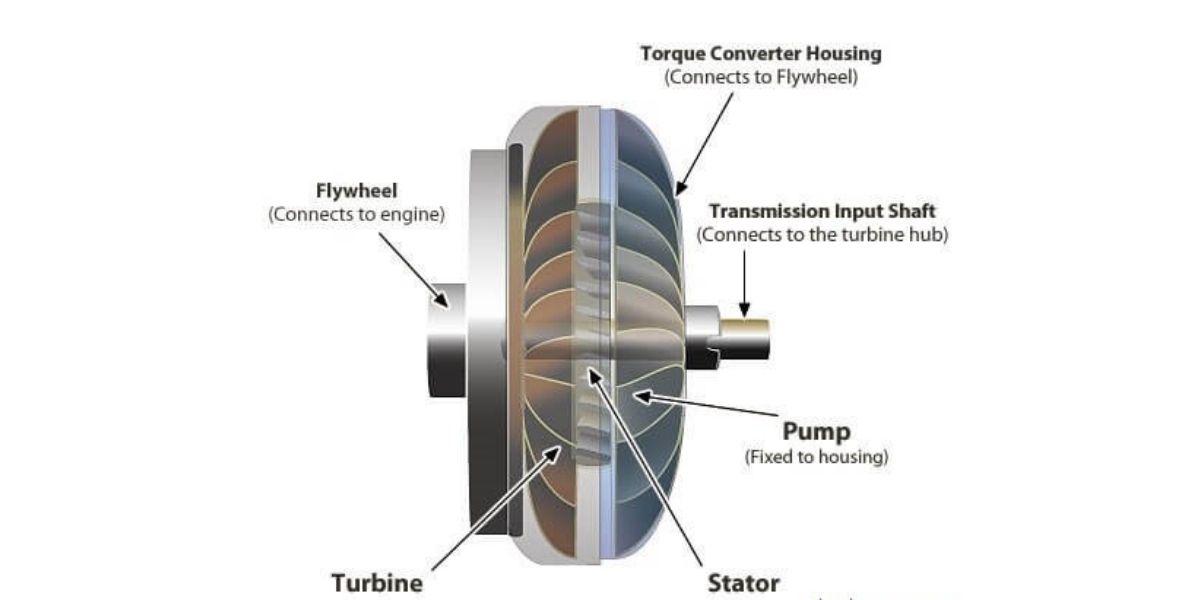
A hydrodynamic torque converter is a fluid drive that sits between an engine and a gearbox and, unlike a plain fluid coupling, multiplies torque: a typical car converter delivers about 1.8 to 2.5 times engine torque at stall, falling to 1:1 as the output speeds up. It has three bladed elements running in oil, the impeller (pump), the turbine and the stator (reactor), and most modern units add a lock-up clutch. It is also called a hydraulic torque converter, and it is the heart of a hydrodynamic transmission such as a conventional automatic gearbox.
Torque converter vs fluid coupling: the stator is the difference
A fluid coupling has only an impeller and a turbine. Oil flung outward by the impeller strikes the turbine blades, drives the turbine, and flows back to the impeller. Because nothing else pushes on the oil, output torque always equals input torque. The coupling can only slip; it can never multiply.
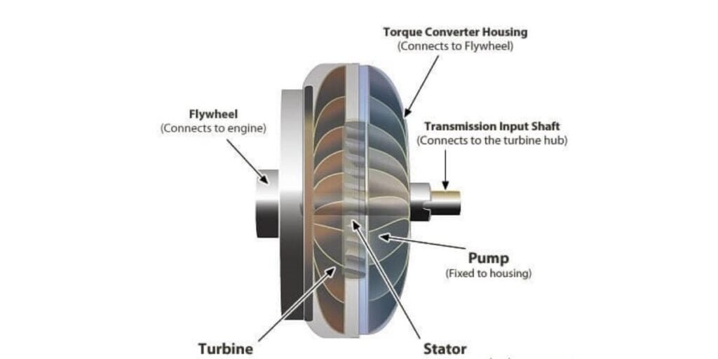
The torque converter adds a third bladed wheel, the stator, in the path of the oil returning from the turbine to the impeller. The stator is mounted on a one-way (overrunning) clutch fixed to the gearbox housing. At low output speeds the oil leaving the turbine is heading the wrong way and would oppose the impeller. The stator, held stationary by its one-way clutch, turns that flow round so it enters the impeller in the direction of rotation. Because the stator is anchored to the housing, it takes a reaction torque, and by torque balance:
Turbine torque = impeller (engine) torque + stator reaction torque
That extra stator torque is where the multiplication comes from. Remove the stator, or let it spin freely, and the converter behaves exactly like a fluid coupling.
Parts of a hydrodynamic torque converter
| Element | Connected to | Job |
|---|---|---|
| Impeller (pump) | Converter cover, bolted to the engine flexplate | Curved blades act as a centrifugal pump, throwing oil outward and into the turbine |
| Turbine | Gearbox input shaft | Blades catch the oil stream and turn the gearbox input |
| Stator (reactor) | One-way clutch on a fixed hollow shaft from the gearbox housing | Redirects returning oil so it helps the impeller; supplies the reaction torque that multiplies output torque |
| One-way clutch | Between stator and fixed shaft | Locks the stator against reverse rotation at low speed ratio; lets it freewheel near coupling |
| Lock-up clutch | Turbine hub, pressing against the inside of the cover | Friction clutch that joins turbine directly to the engine at cruising speed, removing slip |
| Oil (ATF) | Supplied and cooled by the gearbox pump and cooler | Transmits the power and carries away heat |
The whole assembly is a sealed, welded doughnut filled with oil. The gearbox oil pump keeps it full and circulates oil through a cooler, because every bit of slip becomes heat.
How a torque converter works: stall, acceleration and coupling
The behaviour is described against the speed ratio, SR = turbine speed / impeller speed, which runs from 0 (vehicle held still) to about 1.
1. Stall (SR = 0)
The engine runs with the brakes on or the vehicle not yet moving, so the turbine is stationary. Oil hits the still turbine and leaves it at the steepest angle, the stator turns it most sharply, and torque multiplication is at its maximum. This is the stall torque ratio: roughly 1.8 to 2.5 for most cars, and up to about 5 for specialised industrial, rail and heavy marine converters. Efficiency is zero here, because the output shaft does no work; all the engine power turns into heat in the oil. The engine speed reached at full throttle with the output held is called the stall speed.
2. Acceleration (SR from 0 to about 0.85-0.9)
As the vehicle moves off, the turbine speeds up. The oil leaves the turbine at a gentler angle, the stator has less turning to do, and torque ratio falls steadily. Efficiency rises from zero, reaches a peak part-way through the range and then begins to drop as the blade angles move away from their design point.
3. Coupling point (SR about 0.9)
When the turbine reaches roughly 90 percent of impeller speed, the oil leaving the turbine starts to strike the back of the stator blades. The one-way clutch releases and the stator freewheels with the flow. From here the torque ratio is 1 and the converter behaves as a plain fluid coupling. Efficiency now equals the speed ratio, so it climbs slowly towards (but never reaches) 100 percent, because some slip is needed to keep oil circulating.
Torque ratio and efficiency curves in words
- Torque ratio (TR) starts at its highest value at stall and falls almost in a straight line to 1.0 at the coupling point, then stays at 1.0.
- Efficiency is TR × SR. It is zero at stall, rises to a hump in the converter range, dips near the coupling point, then follows the straight line η = SR in the coupling range.
- Without a freewheeling stator, TR would continue falling below 1 above the coupling point and efficiency would drop sharply. The one-way clutch is what prevents that.
Worked example: output torque, speed and efficiency
An engine delivers 250 N·m at 2,000 rpm into a converter. Torque ratios below are read from an assumed typical car converter curve.
Input power = T × ω = 250 × (2π × 2,000 / 60) = 250 × 209.4 = 52.4 kW.
| Condition | SR | TR | Turbine speed | Turbine torque | Output power | Efficiency = TR × SR | Heat into oil |
|---|---|---|---|---|---|---|---|
| Stall | 0 | 2.0 | 0 rpm | 500 N·m | 0 | 0 % | 52.4 kW |
| Accelerating | 0.6 | 1.4 | 1,200 rpm | 350 N·m | 44.0 kW | 84 % | 8.4 kW |
| Coupling | 0.9 | 1.0 | 1,800 rpm | 250 N·m | 47.1 kW | 90 % | 5.2 kW |
Check the accelerating row: output power = 350 × (2π × 1,200 / 60) = 350 × 125.7 = 44.0 kW, and 44.0 / 52.4 = 0.84, the same as 1.4 × 0.6. In that condition the stator is carrying a reaction torque of 350 – 250 = 100 N·m.
Two lessons fall out of these numbers. At stall the converter doubles the torque fed into the gearbox, which is why an automatic pulls away strongly without a clutch pedal. But even at the coupling point it wastes about 10 percent of engine power as heat, which is the reason for the lock-up clutch.
Why the converter slips, and why lock-up clutches exist
A fluid drive can only transmit torque if the turbine runs slower than the impeller; that speed difference is what keeps oil circulating between them. So a converter always slips, by a few percent even when cruising. Every percent of slip is lost as heat in the oil and lost fuel.
The lock-up clutch (torque converter clutch) solves this. Above a set road speed, usually once the car is in a higher gear, the gearbox control applies oil pressure to a piston plate faced with friction material, clamping the turbine to the converter cover. Engine and gearbox now turn together with no slip, and efficiency becomes practically 100 percent. Lock-up was introduced on Packard’s Ultramatic in 1949 and is standard on current automatics. Many modern gearboxes also run the lock-up clutch with slight controlled slip to absorb engine vibration. Its facing is a wet friction material similar to the ones described in our page on clutch friction materials.
Applications of hydrodynamic torque converters
- Automatic cars and SUVs: the conventional “torque converter automatic” that sits alongside AMT, CVT and DCT options on the Indian market. See where it fits in the driveline in our guide to parts of a car transmission.
- City buses and trucks: automatic gearboxes for stop-start urban duty, where smooth, clutch-free starts save driver effort and driveline shock.
- Railway locomotives and railcars: diesel-hydraulic transmissions, often built by Voith. Indian Railways’ WDS-4 class is a broad-gauge diesel-hydraulic shunting locomotive built by Chittaranjan Locomotive Works.
- Construction and material-handling machinery: wheel loaders, dozers, graders, forklifts and dumpers, which need high torque at very low speed and protection from shock loads.
- Marine and industrial drives: marine propulsion systems, crushers, conveyors and pumps, where soft starting and torque multiplication help.
Advantages and limitations
| Advantages | Limitations |
|---|---|
| Multiplies torque at low speed, so fewer gear ratios are needed | Slip wastes power as heat unless locked up |
| Smooth, automatic take-off with no clutch pedal | Needs an oil pump and cooler; overheating is a risk when towing or climbing slowly |
| Damps torsional vibration and shock loads, protecting engine and driveline | Heavier, bulkier and costlier than a dry clutch |
| No friction wear in the fluid drive itself | Lower fuel economy than a manual or DCT in stop-start driving |
| Engine cannot stall when the vehicle stops in gear | Vehicle creeps forward at idle in gear |
Fluid coupling vs torque converter
| Point | Fluid coupling | Torque converter |
|---|---|---|
| Elements | Impeller and turbine | Impeller, turbine and stator (plus lock-up clutch) |
| Torque ratio | Always 1 (output torque = input torque) | About 1.8 to 2.5 at stall in cars; falls to 1 at the coupling point |
| Efficiency | Equal to speed ratio | TR × SR; equals SR above the coupling point |
| Blades | Usually straight radial vanes | Curved blades designed for multiplication |
| Main use | Soft-start industrial drives, conveyors, older automatics | Automatic vehicles, locomotives, construction machines |
Torque converters and fluid couplings are part of the automobile engineering syllabus in the AICTE model curriculum for B.Tech mechanical and automobile engineering.
FAQs
What is a hydrodynamic torque converter?
It is a fluid drive with an impeller, a turbine and a stator running in oil. It transmits engine power to the gearbox through the moving oil and multiplies torque at low output speed, typically about 2 times at stall in a car.
What does the stator do in a torque converter?
It redirects oil returning from the turbine so that it helps the impeller instead of opposing it. Held still by a one-way clutch, it takes a reaction torque that adds to the output torque. Near the coupling point it freewheels.
Is a hydraulic torque converter the same as a hydrodynamic torque converter?
Yes, in everyday use. Both terms describe a converter that works by the kinetic energy of moving oil. Strictly, “hydrostatic” drives, which use pumps and motors working on oil pressure, are a different device.
What is the coupling point of a torque converter?
It is the speed ratio, roughly 0.9, at which torque multiplication stops and the stator starts to freewheel. Above it the converter acts as a fluid coupling with a torque ratio of 1.
Why do torque converters have a lock-up clutch?
Because a fluid drive always slips a little, wasting power as heat. The lock-up clutch mechanically joins the turbine to the engine at cruising speed, removing slip and improving fuel economy.
Both the torque converter and fluid flywheel are devices used in the automotive industry to transfer power from the engine to the transmission, and both utilize hydraulic fluid (usually transmission fluid) as a medium for this power transfer. However, there are fundamental differences between the two:
Function and Components:
Fluid Flywheel: It primarily consists of two bladed components – the primary (driving) impeller connected to the engine, and the secondary (driven) turbine connected to the transmission. The primary purpose of the fluid flywheel is to smoothen the power delivery from the engine to the transmission. When the engine rotates the impeller, it flings fluid outward due to centrifugal force. This moving fluid then causes the turbine to rotate and thereby transmits the power.
Torque Converter: This is a more complex device with at least three main components – the impeller (or pump), the turbine, and the stator. The stator is an additional component that redirects the flow of the fluid between the impeller and turbine, which improves efficiency and amplifies torque. This means a torque converter not only transmits power but can also multiply torque, giving it an advantage during low-speed operations like vehicle take-off.
Torque Multiplication:
Fluid Flywheel: It does not provide torque multiplication. The torque output is essentially the same as the torque input, with some minor losses due to fluid resistance and slippage.
Torque Converter: It can provide torque multiplication, especially at low speeds. This is due to the presence of the stator, which redirects fluid flow in such a way that torque is increased when there is a significant difference in rotational speeds between the engine and transmission, such as during vehicle take-off.
Efficiency:
Fluid Flywheel: There’s always some amount of “slippage” in a fluid flywheel due to the nature of fluid dynamics, which can lead to a bit of inefficiency in power transfer.
Torque Converter: Modern torque converters often come equipped with a lock-up clutch. Once a certain speed is achieved, this clutch can directly connect the engine and the transmission, eliminating the slippage and making the power transfer nearly as efficient as a direct mechanical connection.
Applications:
Fluid Flywheel: These are now somewhat outdated and were primarily found in earlier automatic and semi-automatic transmissions.
Torque Converter: They are commonly used in modern automatic transmissions because of their ability to multiply torque and adapt to varying engine and transmission speeds.
what is the difference between torque converter and fluid flywheel