📌 Quick Answer
HAWTs (horizontal-axis wind turbines) have a rotor spinning about a horizontal axis facing the wind and are the most common, efficient large turbines; VAWTs (vertical-axis wind turbines) spin about a vertical axis and accept wind from any direction.
Key design factors include rotor orientation, efficiency, yaw control, tower height and turbulence handling.
🔹 Key Takeaways
- HAWT — horizontal axis, blades face the wind, needs yaw control; most efficient.
- VAWT — vertical axis, accepts wind from any direction, no yaw needed.
- HAWTs need tall towers and steady wind; VAWTs suit turbulent, urban sites.
- Design considerations: efficiency, height, turbulence, maintenance access, cost.
(HAWTs) – Design Considerations
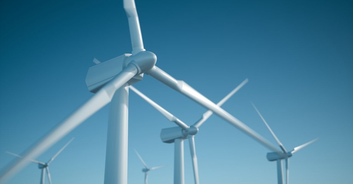
HAWTs stands for Horizontal Axis Wind Turbines, which are the most common type of wind turbines used for converting wind energy into electrical power. These turbines have a horizontal axis of rotation, with the blades spinning around a central hub. HAWTs are widely used for generating electricity in wind farms due to their efficiency and scalability.
Key components:
- Rotor Blades: The blades are airfoils that capture the energy from the wind and convert it into rotational energy. They are usually made of composite materials and come in various lengths, shapes, and designs to optimize energy capture.
- Hub: The hub connects the rotor blades to the main shaft, allowing them to rotate as a single unit. It also houses the pitch control mechanism, which adjusts the angle of the blades to optimize power production.
- Gearbox: In most HAWTs, a gearbox is used to increase the rotational speed of the blades and transmit the power to the generator at higher speeds. However, some modern designs use direct-drive systems, eliminating the need for a gearbox.
- Generator: The generator converts the rotational energy of the blades into electrical energy. It is usually located in the nacelle, which is the housing atop the tower.
Aerodynamic Design:
Blade profile and airfoil selection: The aerodynamic design of the rotor blades is crucial for efficient energy capture. Engineers carefully select airfoil shapes and blade profiles to optimize lift and minimize drag, which ultimately determines the turbine’s performance.
Lift and drag considerations: The lift force is generated by the pressure difference between the upper and lower surfaces of the blade’s airfoil as wind flows over it. This lift force contributes to the rotation of the blades. Drag, on the other hand, is the resistance force experienced by the blades as they move through the air. Engineers aim to maximize lift and minimize drag to improve overall turbine efficiency.
Wind tunnel testing: Before constructing full-scale wind turbines, small-scale models are tested in wind tunnels to evaluate their aerodynamic performance. Wind tunnel testing helps identify potential design improvements and ensures that the final turbine design is efficient and stable under various wind conditions.
Structural Design:
Material selection: HAWTs are subjected to significant stresses and loads due to wind forces and their rotating nature. Engineers carefully choose materials, often composites or metals, that offer a balance of strength, weight, and durability to withstand these forces over the turbine’s operational lifespan.
Stress and fatigue analysis: The structural components, including the blades, hub, tower, and supporting structures, undergo stress and fatigue analysis to ensure their integrity and safety during their operational lifetime. Continuous cyclic loading from wind forces requires a thorough analysis of potential fatigue failure to prevent unexpected damage.
Tower design: The tower provides support and elevation for the wind turbine components. The height of the tower is determined based on the wind conditions at the site and the desired power output. The tower’s design must also account for factors like wind-induced vibrations and tower resonance.

Site Considerations:
Wind speed and direction: The success of a wind farm heavily depends on the wind resource at the site. Engineers perform detailed wind resource assessments to determine the average wind speed, direction, and turbulence intensity. This data helps in optimizing the turbine layout and selecting appropriate turbine models.
Environmental impact: Before constructing wind farms, an environmental impact assessment is conducted to evaluate potential effects on local ecosystems, wildlife, and nearby communities. This assessment helps ensure that wind farms are developed responsibly, minimizing negative impacts on the environment.
Grid integration: Wind farms need to integrate with the existing electrical grid to deliver the electricity they generate. Engineers work to ensure that the wind farm’s power output is stable and consistent, adhering to grid requirements and regulations for reliable power transmission. Grid integration may involve implementing energy storage systems and smart grid technologies to manage fluctuations in wind power output.
Sure! Let’s take a look at Vertical Axis Wind Turbines (VAWTs) and the key considerations in their design.
Overview of VAWTs
Description and Common Usage
Vertical Axis Wind Turbines consist of blades revolving around a vertical axis, in contrast to Horizontal Axis Wind Turbines (HAWTs), where the rotation occurs around a horizontal axis. VAWTs can capture wind from any direction and are often used in urban environments due to their compactness and lower height requirements.
Types
- Savonius: This is a drag-type VAWT, using scoops to catch the wind. It’s relatively inefficient but offers good torque at low wind speeds, making it suitable for small applications like water pumping.
- Darrieus: This lift-type VAWT uses airfoil-shaped blades to convert wind energy into rotational mechanical energy. It has higher efficiency but can struggle with self-starting.
Aerodynamic Design
Blade Shape and Orientation
Blade shape and orientation play a critical role in the performance of VAWTs. Blade profiles need to be designed to efficiently convert wind energy into rotational motion.
Start-up Wind Speed
VAWTs often require specific wind speeds to start turning, so the blade design must be optimized to achieve self-starting at the lowest possible wind speed.
Torque Ripple
Torque ripple refers to fluctuations in torque during the turbine’s operation, leading to vibrations and wear. The design must consider smoothing the torque to reduce mechanical stress.
Structural Design
Support Structure
The support structure must be robust and lightweight to withstand wind forces and vibrations while minimizing material costs.
Durability and Longevity
Designing for durability is key to ensuring a long life span, as VAWTs are exposed to constant fatigue loading and environmental effects.
Material Innovation
New materials and manufacturing techniques can improve efficiency, reduce weight, and enhance durability, offering opportunities for design optimization.
Site Considerations
Urban Applications
VAWTs are well-suited for urban areas due to their compact footprint, reduced noise, and the ability to capture turbulent winds between buildings.
Noise and Visual Impact
VAWTs usually have a less visual impact than HAWTs and can be designed to operate quietly, making them suitable for residential areas.
Bird and Wildlife Considerations
The vertical orientation and slower blade speed of VAWTs may reduce the risk to birds and other flying wildlife. Nonetheless, studies and local regulations must be considered to minimize potential impacts.
Certainly! Horizontal Axis Wind Turbines (HAWTs) and Vertical Axis Wind Turbines (VAWTs) are two main types of wind turbines, each having its own unique characteristics, advantages, and disadvantages. Below is a detailed comparison between these two types of wind turbines in the mentioned categories.
Efficiency: Compare efficiency levels and energy output
- HAWTs:
- Efficiency: HAWTs are generally more efficient, converting up to 35-45% of wind energy into electricity.
- Energy Output: Higher energy output is possible because the blades are often positioned high above the ground where wind speeds are greater.
- VAWTs:
- Efficiency: VAWTs are less efficient, converting around 10-20% of wind energy.
- Energy Output: Generally lower due to their design and the fact that they capture wind closer to the ground where wind speeds may be less.
Cost: Installation, maintenance, and lifecycle costs
- HAWTs:
- Installation: Generally higher due to the size and complexity of the infrastructure.
- Maintenance: Regular maintenance is required due to complex mechanical parts, which can be expensive.
- Lifecycle Costs: Despite higher initial costs, efficiency and output can often lead to favorable lifecycle costs.
- VAWTs:
- Installation: Generally lower since they are simpler to construct and often smaller in size.
- Maintenance: Lower maintenance costs due to less complex mechanics.
- Lifecycle Costs: Even though upfront and maintenance costs are often lower, lifecycle costs might be higher when taking efficiency into account.
Flexibility: Suitability for different locations and wind conditions
- HAWTs:
- Require consistent and strong wind directions, generally more suitable for open fields or offshore installations.
- Less suited for turbulent or highly variable wind conditions.
- VAWTs:
- More flexible in terms of wind direction and can operate in turbulent winds.
- Can be suitable for urban or limited-space environments.
Environmental Impact: Comparison of the environmental footprint
- HAWTs:
- Larger visual footprint and potentially more harmful to bird populations.
- Noise levels can be higher.
- VAWTs:
- Generally more wildlife-friendly, especially to birds.
- Lower visual impact and often quieter.
Innovation and Future Trends: Highlight current research and potential improvements
- HAWTs:
- Research into materials and aerodynamics to improve efficiency and reduce costs.
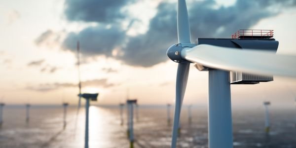
- Offshore wind farms are a significant area of growth, with floating turbines becoming more common.
- VAWTs:
- Continued development in the design to enhance efficiency, including innovative blade designs.
- The growing interest in small-scale urban wind energy solutions.
Also, read Welding defects
Frequently Asked Questions
What is the difference between HAWT and VAWT?
A HAWT rotates about a horizontal axis and must face the wind (using yaw control), while a VAWT rotates about a vertical axis and works with wind from any direction.
Which is more efficient, HAWT or VAWT?
HAWTs are generally more efficient and are used for large-scale power generation; VAWTs are less efficient but simpler and better for turbulent, low-wind or urban sites.
What are the main design considerations for wind turbines?
Rotor orientation, aerodynamic efficiency, tower height, yaw/control system, turbulence and wind variability, structural loads, and ease of maintenance.
Why do most large wind farms use HAWTs?
Because HAWTs capture more energy with higher efficiency at the steady, high-altitude winds available on tall towers in open sites.
Related Topics on EngineeringHulk
- 👉 Difference Between Renewable and Non-Renewable Resources
- 👉 Geothermal Energy – Advantages & Disadvantages