
An ultrasonic machining (USM) machine is a chain of six blocks: a high-frequency generator drives a transducer, whose vibration is amplified by a booster and a horn and passed to a shaped tool that hammers abrasive slurry into the workpiece at about 19-25 kHz. A slurry system feeds the abrasive into the gap, and a feed mechanism keeps the tool pressed lightly against the work. This page explains the USM diagram and the construction of each block, so you can draw and label it in an exam answer.
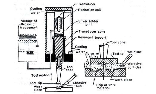
Ultrasonic machining diagram: the blocks in order
Read the diagram from top to bottom, the way energy flows:
- High-frequency generator (a box at the side): turns 50 Hz mains power into an electrical signal at ultrasonic frequency.
- Transducer (top of the vertical stack): turns the electrical signal into mechanical vibration along its axis.
- Booster (optional, directly under the transducer): a short metal section that raises or lowers the amplitude and provides a clamping point.
- Horn (tapered or stepped block): amplifies the amplitude and concentrates it at the small end.
- Tool (fixed to the horn tip): the shape to be reproduced in the work.
- Workpiece (clamped on the table below the tool), with a small gap between tool and work.
- Slurry nozzle (pointing at the gap), fed from a slurry tank with pump and cooling, with a return tray under the work.
- Feed mechanism (acting on the whole acoustic head): lowers the head and applies a steady static force as material is removed.
How to draw the USM diagram in an exam
- Draw one vertical centre line and stack the transducer, booster, horn and tool on it. The horn must visibly narrow towards the tool.
- Put the generator to one side with two wires to the transducer, and mark it “HF generator, about 20 kHz”.
- Draw the workpiece on a fixture or table, with a tiny gap under the tool and abrasive grains shown as dots in the gap.
- Draw the nozzle aimed at the gap, and a tank with a pump below the table, with arrows showing slurry going in and returning.
- Show a double-headed arrow at the tool tip for vibration and a downward arrow on the head for feed force.
- Label cooling water to the transducer if it is magnetostrictive.
- Write the three key numbers next to the diagram: frequency about 20 kHz, amplitude at the tool about 10-50 µm, abrasive grit about 15-150 µm. Examiners look for them.
Construction of each element
1. High-frequency generator
An electronic power supply (oscillator and amplifier) that converts 50 Hz single- or three-phase mains into a sinusoidal output at the resonant frequency of the stack, commonly around 20 kHz. Modern generators track the resonance automatically, because the stack’s natural frequency drifts as the tool warms, wears or is loaded. Output power is adjustable to suit the tool size.
2. Transducer
The transducer converts electrical energy into longitudinal vibration. Two types are used.
Piezoelectric transducer (most modern machines). Its core is a stack of ring-shaped discs of a piezoceramic, usually lead zirconate titanate (PZT). Thin metal electrode shims sit between the rings, and neighbouring rings are polarised in opposite directions so they all expand and contract together. The ring stack is clamped between a heavy steel back mass and a lighter front mass of aluminium or titanium by a central prestress bolt. This “sandwich” (Langevin) construction keeps the brittle ceramic in compression, so it does not crack when it vibrates. Piezoelectric transducers are efficient and need only air cooling.
Magnetostrictive transducer (older and heavy-duty machines). This is a stack of thin nickel (or nickel-alloy) laminations, wound with a coil. When the coil current alternates, the magnetic field changes and nickel shortens and lengthens slightly (magnetostriction). A steady DC bias current is added so that the stack vibrates at the drive frequency rather than twice it. The core is laminated, like a transformer core, to cut eddy-current losses, but it still gets hot and needs water cooling. It is less efficient than a piezoelectric stack.
3. Booster
A half-wavelength metal section between transducer and horn, usually titanium or aluminium alloy. A booster with a larger input diameter than output diameter raises the amplitude (for example 1:1.5); one with the reverse lowers it. Its flange sits at a vibration node, where the metal does not move, so the whole acoustic stack can be clamped there without damping the vibration.
4. Horn (concentrator or sonotrode)
The horn is a solid metal bar, designed to be exactly half a wavelength long so that it resonates. Its length follows from the speed of sound in the bar, c = √(E/ρ). For titanium alloy Ti-6Al-4V, with E ≈ 114 GPa and ρ ≈ 4,430 kg/m3, c ≈ 5,070 m/s, so at 20 kHz half a wavelength is 5,070 / (2 × 20,000) ≈ 0.127 m, about 127 mm. Horns are made from titanium alloy (high fatigue strength, low losses), aluminium alloy, Monel or stainless steel.
Why a horn amplifies. The same vibrational force passes through every cross-section. Where the section is smaller, the same force produces more strain and so a bigger displacement. The profile decides how much gain you get:
| Horn profile | Amplitude gain (ideal) | Notes |
|---|---|---|
| Stepped | Area ratio, (D1/D2)2 | Highest gain; stress concentrates at the step, so a generous fillet radius is needed |
| Exponential | Diameter ratio, D1/D2 | Low gain, but stress spreads smoothly along the length |
| Conical | Less than a stepped horn of the same end sizes | Easy to machine; gain depends on the taper |
Worked example: amplitude gain through the stack
Problem: A transducer face vibrates with an amplitude of 5 µm. It drives a 1:1.5 booster and then a stepped horn whose large end is 40 mm and small end 20 mm in diameter. Find the amplitude at the tool.
- After the booster: 5 × 1.5 = 7.5 µm.
- Stepped horn gain = (D1/D2)2 = (40/20)2 = 4.
- Amplitude at the tool: 7.5 × 4 = 30 µm, which lies in the usual 10-50 µm working range.
An exponential horn with the same end diameters would give a gain of only 40/20 = 2, or 15 µm at the tool. These are ideal figures; the tool’s mass lowers the real gain slightly.
5. Tool
- Material: a tough, ductile metal such as mild steel, stainless steel or other low-carbon steel. It must not be hard: the abrasive should chip the brittle work, while the ductile tool deforms slightly and wears slowly.
- Shape: the negative of the cavity to be cut, made slightly smaller to allow for the overcut produced by the grains rolling at the sides (roughly one grain diameter per side). Hollow tools are used for large holes so less material has to be removed and slurry can reach the centre.
- Attachment: the tool is silver-brazed or soft-soldered to the horn tip, or screwed on with a threaded stud for quick changes. The joint sits at the vibrating tip and must be stiff and void-free, or it will fail by fatigue.
- Size and mass: kept short and light, because extra mass at the tip detunes the horn and cuts the amplitude.
6. Slurry system
- Composition: abrasive grains of boron carbide (B4C), silicon carbide (SiC), aluminium oxide (Al2O3) or diamond, suspended in water, around 30% abrasive by volume as a starting point.
- Delivery: a pump draws slurry from a tank and a nozzle directs it into the tool-work gap. A stirrer or recirculation keeps the grains from settling.
- Return and cooling: slurry drains back to the tank through a tray around the work. The tank is cooled, as the vibration heats the slurry, and the abrasive is replaced as the grains blunt and break down.
7. Feed mechanism
The whole acoustic head (transducer, booster, horn and tool) is mounted on a vertical slide, much like a drill-press quill. A counterweight, spring, pneumatic cylinder or servo motor applies a small, steady static force so the tool follows the cut as material is removed. The head is held at the booster’s nodal flange so the clamp does not absorb vibration.
Working of ultrasonic machining, step by step
- The workpiece is clamped under the tool, and the slurry supply is started so abrasive fills the gap.
- The generator converts mains power to a high-frequency signal (about 20 kHz) and feeds it to the transducer.
- The transducer vibrates along its axis with an amplitude of a few micrometres.
- The booster and horn amplify this to about 10-50 µm at the tool face.
- The feed mechanism brings the tool close to the work under a light static force.
- On each downward stroke the tool strikes the abrasive grains and drives them into the work surface. In a brittle material this chips off tiny particles; there is little heat and no chemical or electrical action.
- On each upward stroke fresh slurry flows into the gap and carries the debris away.
- This repeats about 20,000 times a second, so the tool shape is gradually reproduced in the work as a hole or cavity of slightly larger size.
Parameters, MRR and applications
This page covers the diagram and construction. How frequency, amplitude, grit size, slurry concentration and feed force affect the material removal rate and surface finish, the MRR relation with worked examples, suitable materials, advantages, limitations and the USM vs AJM vs EDM comparison are all in our main article on the ultrasonic machining process. For where USM fits among other methods, see material removal techniques in manufacturing, and for a recent research overview, this review of ultrasonic machining research.
FAQs
What are the main parts shown in an ultrasonic machining diagram?
High-frequency generator, transducer, booster, horn, tool, workpiece, abrasive slurry nozzle with tank and pump, and the feed mechanism that applies a static force to the tool head.
What is the function of the horn in USM?
The horn amplifies the small vibration from the transducer and focuses it at the tool. A stepped horn gives a gain equal to the area ratio of its ends; an exponential horn gives about the diameter ratio.
Which transducer is used in ultrasonic machining?
Most modern machines use piezoelectric transducers made of PZT ceramic rings clamped in a bolted stack. Older or heavy-duty machines use magnetostrictive transducers of laminated nickel, which need water cooling.
Why is the USM tool made of a ductile material?
So that the abrasive chips the hard, brittle workpiece while the tough tool only deforms slightly and wears slowly. Mild steel and stainless steel are common choices.
How is the tool attached to the horn?
By silver brazing or soft soldering, or with a threaded stud screwed into the horn tip. The joint must be stiff and sound so it does not fail by fatigue.