 EngineeringHulk
- Home
- Blog
- Manufacturing Engineering
- Venturi Meter: Working Principle, Construction and Discharge Formula
Venturi Meter: Working Principle, Construction and Discharge Formula
On this page
- The geometry of a venturi meter: three cones and why their angles differ
- Construction and materials
- Working principle: continuity plus Bernoulli
- Worked example with units
- Why the coefficient of discharge is 0.95 to 0.99
- Types of venturi meter
- Cavitation at the throat: the limit nobody warns you about
- Installation and straight-run requirements
- Venturi meter compared with the other flow meters
- Advantages and limitations
- Applications
- References
- FAQs
- Related Topics on EngineeringHulk
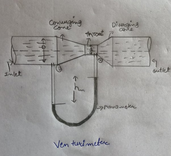
A venturi meter measures the flow rate in a full pipe by squeezing the fluid through a narrow throat and reading the pressure drop that the speed-up produces. It has three parts in series: a short converging cone with an included angle of about 21 degrees, a cylindrical throat, and a long diverging cone of only 5 to 7 degrees. That shallow exit cone is the whole point of the device, because it gives the pressure back gradually and leaves a permanent loss of just 10 to 20 percent of the measured differential.
An orifice plate measuring the same flow throws away 50 to 80 percent of its differential forever. That single difference is why a venturi meter is chosen for large water mains, pump test rigs and any line where pumping energy costs real money, even though it costs several times more and takes up a metre or more of pipe.
The geometry of a venturi meter: three cones and why their angles differ
Almost everything a venturi does well comes out of its shape, so the geometry is worth taking before the theory.
| Section | Typical geometry | What happens to the flow |
|---|---|---|
| Inlet (entrance cylinder) | Same bore as the pipe, D, with the upstream pressure tapping in this section | Flow arrives at pipe velocity. This is section 1 in every formula below. |
| Converging cone | Included angle 21 degrees plus or minus 1 degree in ISO 5167-4; older textbooks quote 20 to 22 degrees | Area falls, so velocity rises and static pressure falls. A favourable pressure gradient here presses the boundary layer flat against the wall, so the flow cannot separate. |
| Throat | Diameter d, length equal to one throat diameter; throat tapping placed at its mid-length | Velocity is at its maximum and pressure at its minimum. The short parallel length lets the profile settle before the tapping reads it. |
| Diverging cone (diffuser) | Included angle of 5 to 7 degrees for best recovery; ISO permits up to 15 degrees in short-form designs | Area grows again, velocity falls and pressure climbs back. This is an adverse pressure gradient, which is the dangerous one. |
The diameter ratio, beta = d/D, usually sits between about 0.3 and 0.75. Beta decides how big the differential is for a given flow: a smaller throat gives a stronger, easier-to-read signal but a lower throat pressure.
Why the divergent cone is four to five times longer than the convergent cone
A converging flow is stable. Fluid is accelerating, pressure drops in the direction of travel, and the slow layer at the wall keeps getting pushed along. You can squeeze hard and fast without trouble, which is why the inlet cone is allowed a steep 21 degrees and stays short.
A diverging flow is the opposite. The fluid decelerates and pressure rises in the direction it is trying to travel, so the slowest fluid of all, the layer touching the wall, is pushed backwards. Open the cone too fast and that layer stalls, reverses, and the main jet tears away from the wall. This is boundary-layer separation, and it fills the cone with eddies that turn the kinetic energy you wanted back into heat and noise.
Keeping the included angle down near 5 to 7 degrees means the pressure rises slowly enough along the wall that the boundary layer survives the trip. The cost is length: recovering the same area change at 6 degrees instead of 21 takes roughly four times the axial distance, which is why a classical venturi is a long, heavy casting. The payback is the permanent loss figure, 10 to 20 percent of the differential against 50 to 80 percent for a sharp-edged plate, where the jet separates by design and no one tries to recover anything.
Construction and materials
A classical venturi tube is built as one flanged spool piece that bolts into the line. The three types recognised in practice differ by how that spool is made:
- Machined. The full profile is machined from bar or a casting, usually in bronze, gunmetal or stainless steel. The best surface finish and the highest discharge coefficient, used on small and medium bores and on laboratory rigs.
- As-cast. Cast iron or cast steel with the convergent cone and throat machined and the divergent cone left as cast. The normal choice for medium and large water mains.
- Rough-welded sheet. Cones rolled from plate and welded into a fabricated body, often lined. The only economic option on very large mains, where a casting would be impossible to handle.
The pressure tappings matter as much as the profile. A classical venturi does not use a single hole at each section; it uses several small, square-edged, burr-free tappings spaced around the circumference and joined into an annular chamber called a piezometer ring, so the instrument reads the average pressure round the pipe rather than whatever one hole happens to see. The two rings feed a U-tube manometer or a differential pressure transmitter through impulse lines.
Materials follow the fluid: bronze and stainless for clean water and chemicals, cast iron for municipal water, rubber or ceramic lining for slurries. With no sharp edge anywhere in a venturi, abrasive fluids wear it far more slowly than they blunt an orifice plate.
Working principle: continuity plus Bernoulli
Two equations do all the work. Continuity says the same volume per second passes every section, so a smaller area forces a higher velocity. Bernoulli says that for steady, incompressible, effectively frictionless flow the total head stays constant, so the velocity the throat gains is paid for out of pressure.
Take section 1 in the inlet and section 2 at the throat. For a horizontal meter, Bernoulli gives:
p1/ρg + V1²/2g = p2/ρg + V2²/2g
Call the pressure head difference h = (p1 – p2)/ρg, which is what the manometer actually shows. Then:
h = (V2² – V1²) / 2g
From continuity, A1V1 = A2V2, so V1 = A2V2/A1. Substituting:
2gh = V2² (1 – A2²/A1²) = V2² (A1² – A2²) / A1²
Rearranging for the throat velocity and multiplying by the throat area gives the theoretical discharge, and putting the discharge coefficient in front turns it into the real one:
Q = Cd × A1A2 √(2gh) / √(A1² – A2²)
One point students lose marks on: the formula is not limited to horizontal meters. For a vertical or inclined venturi, h is the difference in piezometric head, (p/ρg + z) at section 1 minus the same at section 2. A U-tube manometer across the two tappings measures exactly that combination, so the elevation terms cancel in its own legs and the reading does not care how the meter is tilted.
Turning a manometer reading into head of flowing fluid
A mercury manometer does not read metres of water directly. If the deflection is x, the manometer liquid has specific gravity Sm and the flowing fluid has specific gravity So, then:
h = x (Sm/So – 1)
For mercury over water, Sm/So = 13.6, so every millimetre of mercury deflection is 12.6 mm of water head. If the manometer liquid is lighter than the flowing fluid and sits in an inverted U-tube, the bracket becomes (1 – Sm/So).
Worked example with units
Problem. A horizontal venturi meter has a 300 mm inlet and a 150 mm throat and carries water. A mercury differential manometer across the tappings deflects 250 mm. Take Cd = 0.98. Find the discharge and the throat velocity.
- Areas. A1 = (π/4)(0.30)² = 0.070686 m². A2 = (π/4)(0.15)² = 0.017671 m². Beta = 0.5.
- Head. h = 0.250 (13.6/1 – 1) = 0.250 × 12.6 = 3.15 m of water.
- Velocity term. √(2gh) = √(2 × 9.81 × 3.15) = √61.80 = 7.862 m/s.
- Area term. A1² = 4.9965 × 10⁻³, A2² = 3.1228 × 10⁻⁴. Difference = 4.6842 × 10⁻³, and its square root is 0.068441 m².
- Discharge. Q = 0.98 × (0.070686 × 0.017671 × 7.862) / 0.068441 = 0.1406 m³/s, which is 140.6 litres per second or about 506 m³/h.
- Velocities. V1 = 0.1406/0.070686 = 1.99 m/s and V2 = 0.1406/0.017671 = 7.96 m/s, four times the pipe velocity because the area is a quarter.
Energy check. The differential is ρgh = 1000 × 9.81 × 3.15 = 30.9 kPa. A venturi gives back most of that, so the permanent loss is roughly 3 to 6 kPa. An orifice plate on the same duty would keep 15 to 25 kPa of it, and on a pump running 8,000 hours a year against 140 L/s that gap is a continuous 2 to 3 kW of wasted shaft power.
Why the coefficient of discharge is 0.95 to 0.99
Cd is the ratio of actual discharge to the theoretical discharge the frictionless derivation predicts. For a classical venturi it runs from about 0.95 to 0.99, with well-machined tubes at the top of the band and as-cast and welded bodies slightly lower. An orifice plate sits near 0.6, and the gap is not a small correction but two different physical situations.
An orifice coefficient absorbs two separate errors: the jet keeps contracting after the hole, so the real minimum area is the vena contracta at roughly 60 to 65 percent of the drilled bore rather than the bore used in the formula, and the free jet then loses energy mixing back into the pipe. Together those give the familiar 0.6.
A venturi has neither problem. The throat is a machined cylinder that the fluid fills completely, so the flow area in the formula is the true flow area and there is no contraction correction at all. What remains is wall friction and a slight non-uniformity of the velocity profile, both small. That is why Cd only has to trim a few percent off the ideal answer, and why it stays almost constant once the throat Reynolds number is above about 2 × 10⁵. For the vena contracta mechanism and the orifice tapping positions in detail, see our separate article on orifice meters rather than repeating it here.
Types of venturi meter
Venturis are grouped two ways, and exam questions ask for both.
By orientation:
- Horizontal venturi meter. The standard case, z1 = z2, and the pressure difference is the whole story.
- Vertical venturi meter. Used in rising mains and on pump delivery lines. The static pressure difference now includes the elevation change, but as shown above the manometer subtracts it out automatically.
- Inclined venturi meter. Same treatment as vertical, with z taken along the true vertical.
By construction: machined, as-cast and rough-welded classical tubes, as above. Two shortened relatives also exist: the venturi nozzle, which replaces the conical inlet with a rounded nozzle profile and keeps a short diffuser, and the Dall tube, a short insert with a step at the throat that gives a high differential in a fraction of the length, at the cost of slightly higher loss.
Cavitation at the throat: the limit nobody warns you about
The throat is the lowest-pressure point in the meter. If the absolute pressure there falls to the vapour pressure of the liquid, the water boils at room temperature and the bubbles collapse violently in the diffuser where pressure recovers. Three things go wrong at once: the calibration is destroyed because the throat is no longer full of liquid, the flow chokes so more differential stops meaning more flow, and the collapsing bubbles pit the metal.
The check is straightforward. For a horizontal meter, p2 = p1 – ρgh in absolute terms. In the worked example the differential was 30.9 kPa, so with the line at 120 kPa absolute the throat sits at about 89 kPa, comfortably clear of the 4.25 kPa vapour pressure of water at 30 degrees C.
The danger comes from shrinking the throat. Throat velocity varies as 1/d² and the head varies as velocity squared, so h grows with the fourth power of the diameter ratio. Halving the throat from 150 mm to 75 mm at the same flow multiplies the 3.15 m head by sixteen, to about 50 m of water or 490 kPa, which drags the throat well below vapour pressure and starts cavitating. Practical defences: keep beta on the larger side, keep the meter low in the system or add downstream back-pressure, and watch hot liquids, because vapour pressure climbs steeply with temperature.
Installation and straight-run requirements
A differential meter measures whatever the velocity profile in front of it allows. Swirl from two out-of-plane bends, or the distorted profile behind a half-open valve, shifts the coefficient by percentages, not fractions of a percent.
- Give the meter straight, unobstructed pipe of the same bore upstream. ISO 5167-4 tabulates the length required against beta and the type of fitting. A venturi needs less than an orifice at the same beta, because its own converging cone helps straighten the flow, but it still needs several diameters and far more behind a bad fitting.
- Allow about four diameters of straight pipe downstream before the next fitting.
- Control valves belong downstream of the meter, never just upstream.
- On liquids, take the tappings from the side or the bottom half of the pipe so air cannot collect in the impulse lines, and slope the lines down to the transmitter. On gases, take them from the top so condensate drains away.
- Install the meter with the pipe running full. A partly full pipe reads nonsense.
- Check the impulse lines for blockage before you blame the meter.
Venturi meter compared with the other flow meters
| Feature | Venturi meter | Orifice meter | Flow nozzle | Rotameter |
|---|---|---|---|---|
| Coefficient of discharge | 0.95 to 0.99 | About 0.6 to 0.65 | About 0.95 to 0.98 | Not applicable, area varies |
| Permanent pressure loss | 10 to 20 percent of differential | 50 to 80 percent | 30 to 60 percent | Low and nearly constant |
| Length needed | Long, often 1 to 3 pipe diameters of body plus a long diffuser | A flange thickness | Short spool | Vertical glass or metal tube |
| Cost | High | Lowest | Medium | Low to medium |
| Dirty or abrasive fluid | Good, no sharp edge to wear | Poor, the edge blunts and Cd drifts | Fair | Poor, needs a clear tube |
| Best suited to | Large mains, high flows, lines where pumping energy matters | Cheap, routine metering of clean fluids | High-velocity and steam service | Small clean flows read locally |
Advantages and limitations
Advantages. Very low permanent head loss, so low running cost. A high, stable discharge coefficient near 0.98, so better than about 1 percent accuracy is achievable on a properly installed meter. No moving parts. It tolerates suspended solids and slurries far better than a plate, and it lasts decades in a water main.
Limitations. Expensive and heavy, and it needs a lot of straight pipe length, which is usually the real obstacle in a crowded plant. It cannot be slipped between existing flanges the way a plate can, and changing beta means changing the whole meter. Like every differential device its output is a square root, so a 10 to 1 flow turndown needs a 100 to 1 differential range and the low end reads poorly. The throat can also cavitate on low-pressure or hot liquids.
Applications
Municipal water supply and treatment plants, where the meter sits in a large main and the low head loss pays for the casting many times over. Pump and turbine test rigs, including the venturi bench in almost every B.Tech fluid mechanics laboratory. Irrigation offtakes and headworks. Power station feedwater, condenser cooling water and air ducts. Slurry, pulp stock and sewage lines where a plate would clog or erode. The same shape, with the throat pressure used to suck in a second fluid instead of to measure the first, is what makes a carburettor venturi, an eductor and a venturi scrubber work.
References
- ISO 5167-4, Measurement of fluid flow by means of pressure differential devices inserted in circular cross-section conduits running full, Part 4: Venturi tubes. The current edition is ISO 5167-4:2022; orifice plates are covered by ISO 5167-2 instead.
- NPTEL – Online Engineering Courses, Fluid Mechanics lecture series on flow measurement.
FAQs
What is the working principle of a venturi meter?
Continuity and Bernoulli’s equation together. The converging cone reduces the flow area, so the fluid speeds up through the throat and its static pressure falls. The pressure difference between the inlet and the throat is measured, and the discharge follows from Q = Cd A1A2 √(2gh) / √(A1² – A2²), where h is the head difference in metres of the flowing fluid.
Why is the diverging cone of a venturi meter longer than the converging cone?
Because pressure rises along the diverging cone, which pushes the slow boundary layer backwards and can make the flow separate from the wall. Keeping the included angle down to about 5 to 7 degrees, instead of the 21 degrees used on the inlet, stops that separation, and a shallower angle needs more length for the same change in area. The reward is that the venturi loses only 10 to 20 percent of its differential permanently.
What is the coefficient of discharge of a venturi meter and why is it higher than an orifice meter’s?
About 0.95 to 0.99, against roughly 0.6 for an orifice plate. The venturi throat is a machined cylinder that the fluid fills completely, so there is no vena contracta to correct for and no free jet mixing back into the pipe. Only wall friction and a small profile effect remain, so Cd is close to one.
Does a venturi meter work if it is installed vertically?
Yes. For a vertical or inclined meter, h is the difference in piezometric head, that is (p/ρg + z) at the inlet minus the same quantity at the throat. A differential manometer connected across the two tappings cancels the elevation terms in its own legs, so the reading and the discharge formula are unchanged.
What causes cavitation in a venturi meter?
A throat pressure that falls to the vapour pressure of the liquid, which happens when the throat is too small, the line pressure too low or the liquid too hot. Vapour bubbles form at the throat and collapse in the diffuser, wrecking the calibration and pitting the metal. Using a larger beta ratio or raising the downstream back-pressure prevents it.
Related Topics on EngineeringHulk
Keep reading
Orifice Meter: Definition, Construction, Working Principle and Discharge Formula
How an orifice meter measures flow: plate types, tappings, the discharge equation with a worked example, Cd values, pressure loss and orifice vs venturi.
Manometer: Working Principle, Types, Formula and Worked Examples
A manometer measures pressure by balancing it against a liquid column, p = rho g h. Working principle, every type, worked examples and reading errors.
Electrical Discharge Machining (EDM): Working, Types and RAM EDM
Electrical discharge machining explained: how spark erosion works, RAM (die-sinking) EDM, wire EDM, hole-drilling and micro-EDM, parameters and uses.
Electrochemical Grinding (ECG): Construction, Working, MRR and Applications
Electrochemical grinding (ECG) explained: construction, working, MRR from Faraday's law with a worked example, parameters, medical uses and ECG vs ECM.
Magneto Ignition System: Working Principle, Parts, Types and Applications
A magneto ignition system makes its own high-voltage spark from an engine-driven magnet, with no battery. Working, parts, types, timing and applications.
Babcock and Wilcox Boiler: Definition, Construction, Working and Applications
Babcock and Wilcox boiler explained: water-tube construction, all parts, working, natural circulation, specifications, advantages and applications.