 EngineeringHulk
- Home
- Blog
- Mechanical Engineering
- Refrigeration Cycle Between a Condenser at 27 C and an Evaporator at -23 C: Solved COP Problem
Refrigeration Cycle Between a Condenser at 27 C and an Evaporator at -23 C: Solved COP Problem
On this page
A refrigeration cycle operating between a condenser temperature of +27 C and an evaporator temperature of -23 C has a Carnot COP of 5: COP = TL / (TH – TL) = 250 / (300 – 250) = 5. The condenser is the part of the cycle where this heat, plus the compressor work, is rejected: refrigerant enters it as a hot, superheated vapour and leaves as a high-pressure liquid, usually slightly subcooled.

The problem
A refrigeration cycle operates between a condenser temperature of +27 C and an evaporator temperature of -23 C. The Carnot coefficient of performance of the cycle will be:
(a) 0.2 (b) 1.2 (c) 5 (d) 6
Solution: Carnot COP
The Carnot (reversed Carnot) refrigerator is the ideal limit. Its COP depends only on the two absolute temperatures:
COPCarnot = TL / (TH – TL)
- Convert to kelvin. TH (condenser) = 27 + 273 = 300 K. TL (evaporator) = -23 + 273 = 250 K.
- Temperature lift = 300 – 250 = 50 K.
- COP = 250 / 50 = 5.
Answer: (c) 5. Using 273.15 instead of 273 gives 250.15 / 50 = 5.003, the same answer.
Why the other options are traps:
- (d) 6 is TH / (TH – TL) = 300 / 50, the COP of a Carnot heat pump between the same temperatures. It is always exactly 1 more than the refrigerator COP.
- (a) 0.2 is (TH – TL) / TL, the formula upside down.
- Putting Celsius values straight in gives -23 / (27 – (-23)) = -0.46, which is meaningless. COP formulas need absolute temperatures.
Extending the problem: work input and heat rejected
Suppose this ideal cycle removes 1 TR (3.517 kW) from the cold space.
- Compressor work W = QL / COP = 3.517 / 5 = 0.703 kW
- Heat rejected in the condenser QH = QL + W = 3.517 + 0.703 = 4.220 kW
Check: QH / W = 4.220 / 0.703 = 6.0, the heat pump COP, as it should be. The condenser always has to reject more heat than the evaporator absorbs, because the compressor’s work also ends up as heat. Real vapour-compression cycles have lower COPs than the Carnot value because of throttling losses, superheat and compressor inefficiency, so real condensers reject even more heat per kW of cooling.
The condenser in the refrigeration cycle
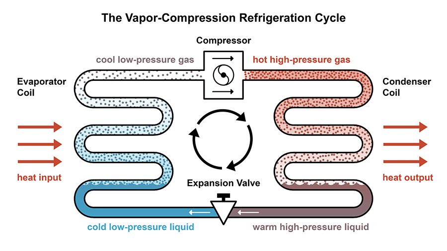
In a vapour-compression cycle the refrigerant flows compressor, condenser, expansion device, evaporator and back to the compressor. The condenser is the high-pressure heat exchanger that dumps heat to the surroundings (outdoor air or cooling water). A full walk-through of the four components is on our page about the vapour compression refrigeration cycle, and where it fits in a building is covered in what is HVAC.
In what state does the refrigerant leave the condenser?
It leaves as a high-pressure liquid: saturated liquid in the ideal cycle, and usually slightly subcooled liquid (a few degrees below its condensing temperature) in a real system. It entered as a high-pressure, high-temperature superheated vapour from the compressor. The pressure stays almost the same through the condenser; only the phase and temperature change.
The three zones inside a condenser
| Zone | What happens | Refrigerant state |
|---|---|---|
| 1. Desuperheating | Hot vapour from the compressor cools down to its saturation (condensing) temperature. Sensible heat only. | Superheated vapour to saturated vapour |
| 2. Condensing | Vapour turns to liquid at constant temperature and pressure, releasing its latent heat. The largest share of the heat is rejected here. | Liquid-vapour mixture, quality falling from 1 to 0 |
| 3. Subcooling | Liquid cools a few degrees below the condensing temperature. Sensible heat only. | Saturated liquid to subcooled liquid |
Subcooling matters for two reasons. It makes sure the expansion device receives only liquid, with no vapour bubbles (“flash gas”) that would upset its metering. It also lowers the enthalpy entering the evaporator, so each kilogram of refrigerant absorbs more heat and the refrigerating effect rises.
Types of condensers
| Type | Heat goes to | Typical condensing temperature | Where used |
|---|---|---|---|
| Air-cooled | Outdoor air blown over a finned coil | Roughly 10-15 C above outdoor air; well above 50 C on a 45 C Indian summer day | Room ACs, VRF, small chillers, refrigerators |
| Water-cooled (shell-and-tube, plate) | Cooling water, usually from a cooling tower | A few degrees above the leaving water temperature; often in the high 30s C | Large chillers in malls, hospitals, plants |
| Evaporative | Water sprayed over the coil while air blows through; water evaporation carries the heat | Close to the outdoor wet-bulb temperature plus a margin, lower than air-cooled | Ammonia cold storages, industrial refrigeration |
These temperatures are typical design values, not fixed rules. The general point holds: water-cooled and evaporative condensers run cooler than air-cooled ones, which is why large plants use them despite the cost of cooling towers and water treatment.
How condenser temperature affects COP
Keep the evaporator at -23 C (250 K) and raise the condensing temperature to 40 C (313 K), as might happen with a dirty air-cooled condenser on a hot day:
- COP = 250 / (313 – 250) = 250 / 63 = 3.97
- Work for 1 TR = 3.517 / 3.97 = 0.886 kW, up from 0.703 kW
- Heat rejected = 3.517 + 0.886 = 4.403 kW
A 13 C rise in condensing temperature cuts the ideal COP from 5 to 3.97 and increases compressor power by 26 percent (5 / 3.97 = 1.26) for the same cooling. That is why technicians clean condenser coils, keep outdoor units out of direct sun and leave space for air to flow, and why cooling tower performance matters in large plants.
| Condenser temperature | TH (K) | Carnot COP (TL = 250 K) | Work per TR (kW) |
|---|---|---|---|
| 27 C | 300 | 5.00 | 0.703 |
| 40 C | 313 | 3.97 | 0.886 |
The same logic works on the cold side: raising the evaporator temperature also shrinks the lift and raises COP. Refrigeration cycles are part of the B.Tech mechanical thermodynamics and RAC syllabus; free lectures are on NPTEL.
FAQs
What is the Carnot COP of a refrigerator working between 27 C and -23 C?
5. Convert to kelvin (300 K and 250 K), then COP = 250 / (300 – 250) = 5.
In what state does the refrigerant leave the condenser?
As a high-pressure liquid: saturated liquid in the ideal cycle, and usually slightly subcooled liquid in real systems. It enters the condenser as a superheated high-pressure vapour.
What does the condenser do in a refrigeration cycle?
It rejects heat to outdoor air or cooling water. The refrigerant is desuperheated, condensed and slightly subcooled, giving up the heat absorbed in the evaporator plus the compressor work.
Why is heat rejected in the condenser more than the refrigeration effect?
Because by the first law QH = QL + W. The compressor’s work is added to the heat picked up in the evaporator, and both leave through the condenser.
How does a higher condenser temperature affect COP?
It lowers COP because the temperature lift grows. With the evaporator at -23 C, raising the condenser from 27 C to 40 C cuts the Carnot COP from 5 to about 3.97 and raises compressor work by about 26 percent.
Related Topics on EngineeringHulk
Keep reading
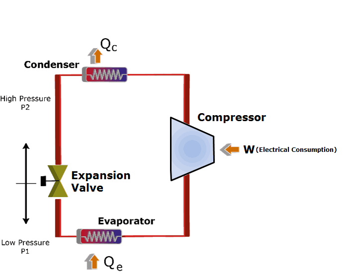
Vapour Compression Refrigeration Cycle: Working, p-h Diagram, COP and Refrigerants
The vapour compression refrigeration cycle explained: four processes, four components, p-h and T-s diagrams, a solved COP example and modern refrigerants.
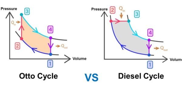
Otto Cycle and Diesel Cycle: Processes, P-V Diagrams, Efficiency and Differences
Diesel cycle vs Otto cycle: the four processes, P-V and T-S diagrams, both efficiency formulas with cut-off ratio, and worked examples at r = 8 and 18.

Volumetric Strain: Definition, Formula and Solved Examples
Volumetric strain is the change in volume over original volume, e_v = ΔV/V. Formulas for bars, cubes, cylinders and spheres, bulk modulus and examples.
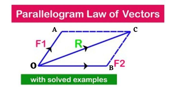
Parallelogram Law of Forces: Statement, Derivation and Solved Examples
The parallelogram law of forces states that two forces at a point have a resultant along the diagonal of a parallelogram. Derivation and solved examples.
Moment of a Force: Formula, Types, Couples and Solved Examples
The moment of a force is its turning effect about a point, equal to force times perpendicular distance. Formula, sign rule, couples and solved examples.

Strain Formula: Definition, Types, Units and Solved Examples
Strain formula: strain = change in length / original length. Units, tensile, shear and volumetric strain, true strain, thermal strain and solved examples.