📌 Quick Answer
An automobile clutch is the device between the engine and gearbox that lets the driver smoothly connect or temporarily disconnect the drive, so the vehicle can start from rest and change gear.
It transmits torque by friction when engaged and interrupts it when the pedal is pressed.
🔹 Key Takeaways
- The clutch couples and uncouples the engine from the transmission.
- It transmits drive by friction between the flywheel, clutch plate and pressure plate.
- Pressing the pedal releases the pressure plate and disconnects the drive.
- Types include single-plate, multi-plate, diaphragm, cone and centrifugal clutches.
Automobile Clutch
In automobiles, power is developed by the engine that is used to turn the wheels. Therefore, the engine must be connected to the transmission systems to transfer power to the wheels. In addition, there must be a system that allows the engine to be engaged and disengaged from the transmission system smoothly and without bumps so that the vehicle mechanism is not damaged and passengers are not uncomfortable. A clutch is used in automobiles for this purpose.
CLUTCH PARTS
1. Flywheel
The flywheel is an important and integral part of the engine, also used as part of the clutch. It is a drive member and connects to the clutch shaft pressure plate, and is housed with bearings in a flywheel. The steering wheel turns as the crankshaft rotates.
2. Pilot bearing
The pilot bearing or bushing presses the end of the crankshaft to support the end of the transmission input shaft. The pilot bearing prevents the driveshaft and clutch disc from swinging up and down when the clutch is released. It also helps center the disc input shaft on the flywheel.
3. Clutch disc or disc Plate
It is the driven part of the single-plate clutch and has friction material on both surfaces. It has a center hub with internal splines to limit axial travel along with the splined gearbox crankshaft. This helps provide dampening actions against torsional vibrations or torque variations between the engine and transmission.
A clutch plate is a plate between the flywheel and the friction or pressure plate. It has a series of liner reversers on each side to increase friction. These clutch linings are made from asbestos material. As a result, they are highly heat resistant.
4. Pressure plate
The pressure plate is made of special cast iron. It is a cumbersome part of the clutch assembly. The primary function of the pressure plate is to establish uniform contact with the front of the driven plate, through which the pressure springs can exert sufficient force to transmit full engine torque.
The pressure plate presses the clutch disc into the flywheel from its machined surface. Pressure springs are mounted between the pressure plate and clutch cover assembly. As a result, pressure will be removed from the steering wheel each time the release levers are pressed through the lever, or the release levers rotate accordingly.
5. Clutch cover
The clutch cover assembly is firmly bolted to the flywheel, and it consists of a pressure plate, release lever system, clutch cover, and pressure springs. Generally, the clutch disc rotates with the flywheel. However, when the clutch is disengaged, the flywheel and pressure plates can rotate independently of the driven plate and driveshaft.
6. Release levers
These pins on the clutch cover pins, their outer ends sit and rest on the pressure plate legs, and the inner ends protrude towards the clutch axis. Therefore, careful and precise adjustment of the release mechanism is one of the most critical factors governing the performance of a clutch assembly.
7. Clutch shaft
It is a component of Transmission. Since there is a splined shaft for the clutch disc hub, it slides over it. One end of the clutch shaft connects to the crankshaft or flywheel, and the other end connects to the gearbox or is part of the gearbox.
The common friction material is an organic composite resin with a copper wire coating or a ceramic material. Ceramic materials can often transmit higher torque loads but can cause increased flywheel wear rates. Previously asbestos was also used in clutch plates.
Requirements of Clutches
The Automobile Clutch is a mechanism that allows transmitting the rotary movement of an axis, when desired, to the second axis whose axis coincides with that of the first.
Clutch Requirements: –
1. Torque transmission: – The clutch must achieve maximum engine torque under all conditions. It is typically designed to transmit 125 to 150% of the engine’s maximum torque.
2. Gradual engagement: – The clutch must move positively in a gradual manner, without sudden jerks.
3. Heat dissipation: – When applying friction, a large amount of heat is generated. Friction surfaces must have sufficient surface and mass to absorb heat.
4. Dynamic balancing: – This is mainly needed in high-speed clutches.
5. Vibration damping: – An appropriate mechanism must be incorporated in the clutch to eliminate the noise produced in the transmission.
6. Dimensions: – The clutch size should be as small as possible to take up as little space as possible.
7. Inertia: – The rotating parts of the clutch must have minimal inertia. Otherwise, when the clutch is released for gear shifting, the clutch disc will continue to rotate, causing complex gear changes and gear collisions despite the synchronizer.
8. Clutch pedal free play: – To reduce the effective clamping load on the carbon thrust bearing and the wear of the carbon thrust bearing, it is necessary to leave good clutch pedal free play in the clutch.
9. Ease of use: – For higher torque transmission, the clutch release operation should not be tiring for the driver.
10. Lightweight: The engaging element of the clutch must be made as light as possible so that it does not continue to rotate for a certain period after the clutch has been disengaged.
Types of Automobile Clutch:
- Friction clutch single plate clutch
- Multiplate clutch
- Wet
- Dry
- Cone clutch
- External
- Internal
- Centrifugal Clutch
- Semi-centrifugal clutch
- Conical spring clutch or Diaphragm clutch
- Tapered finger type
- Crown spring type
- Positive clutch
- Dog clutch
- Spline Clutch
- Hydraulic clutch
- Electromagnetic clutch
- Vacuum clutch
- Overrunning clutch or freewheel unit
Single Plate Clutch:
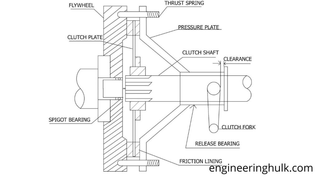
A single-disc clutch is defined as a type of friction clutch consisting of a single clutch disc. The amount of frictional force generated inside the clutch disc is due to the contact between the friction lining mounted on the clutch disc. The reason behind the frictional force is the friction lining, which plays a significant role in friction. The friction seal can be fitted by the manufacturer on both sides of the plate.
Furthermore, a single plate clutch can also be defined as a dry clutch, so no type of lubricant is required for the perfect functioning of the clutch. The friction coefficient is due to the contact between the friction linings, which is very high in a single-plate clutch case.
Parts of a single disc clutch:
Primarily, a clutch is made up of various components, such as a pressure plate, flywheel, disc, friction liner and spring. Therefore, the main features of a clutch concerning its mechanism are briefly mentioned below.
Flywheel:
The last part that a manufacturer can use to develop a clutch is the flywheel. The flywheel is the heaviest part of all the parts incorporated in a clutch.
The flywheel is fixed to the crankshaft, and another side of the flywheel comes into contact with the fixing plate. Furthermore, the steering wheel is the part that decides the time, which must be used by the entire mechanism, as regards engagement and disengagement.
Due to contact with the grip plate, a large amount of torque is often generated, due to which engagement occurs inside the vehicle.
Pressure plate:
The central part that controls the frictional force is the pressure plate. The pressure plate is attached to the solid metal plate. The help of the weight is needed to maintain contact.
In this regard, the pressure plate uses springs attached to the pressure plate to place the right amount of weight. In addition, the pressure plate controls the contact between the friction surfaces of the handle and the flywheel to maintain the amount of friction force.
Friction coating:
It is the central part of the contact form in which the frictional force is produced. The friction seal is attached to the locking plate on both sides of it. The friction lining creates contact with the flywheel and thus creates a frictional force at the moment of rotation.
With the help of this force, the couple produces. The friction coating can also be referred to as the friction surface. In addition, the friction coating is made of a particular type of metal which is of a high coefficient nature and never slips and is made up of the friction surface.
Clutch plate:
The clutch disc is the essential part of a clutch. It is also the central part. In addition, the clutch disc consists of a thin metal plate. It consists of a friction coating on both sides.
Furthermore, the clutch disc is dependent on the operating principle of the friction lining. The clutch disc rotates only, and the attached friction surface can increase friction with the flywheel to produce friction and torque. A clutch plate is also known as a clutch disc.
Springs:
The springs are connected to the pressure plate with the help of screws. These springs often help the clutch disc make contact with the flywheel to produce friction and torque.
In addition, the pressure plate weighs down the springs that are attached to the pressure plate. The springs then hold the flywheel to move forward or backward from the friction surface of the clutch disc to maintain the amount of force created by the friction.
Therefore, the high coefficient of friction is also maintained, and the right amount of torque is produced. Also, these springs cannot be slipped.
Axial ball bearing:
The thrust ball bearing is the central part that assists in rotating the clutch disc and flywheel. It usually consists of a few small bearing balls in a circular ring. It can be used in low thrust. It also helps produce rotation between two parts to keep axial loads low as thrust is low.
Operating principle of the single plate clutch:
The whole principle of operation of a single plate clutch depends on two distinct areas: disengagement and engagement. Therefore, the following section briefly discusses the two mechanisms, one is engagement, and the other is disengagement.
All three parts are required in the clutch. These are the flywheel, a friction plate a clutch plate, and a pressure plate. Some springs provide an axial force perm pressure plate attached to the flywheel. The friction disc is situated between the flywheel and the pressure plate.
When the vehicle driver presses the clutch pedal, the clutch is released, and This action forces the pressure plate to move away from the friction plates against the force of pressure springs. With this action of the pressure plate, the friction plate is released, and thus the clutch disengages.
When the foot is off the pedal, springs push the pressure plate against the clutch disc, pressuring the flywheel. This locks the engine into the transmission input shaft, causing them to rotate at the same speed. The amount of force the clutch can withstand depends on the friction between the clutch disc and the flywheel; force is exerted by the spring on the pressure plate.
As the clutch is depressed, the piston pushes on the release yoke, pressuring the thrust bearing against the center of the diaphragm spring. As the center of the diaphragm spring pushes inward, a series of pins near the outer surface of the spring causes the spring to move the pressure plate away from the clutch disc. This releases the rotating engine clutch.
Multi-plate clutch:
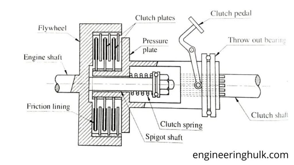
MULTI-PLATE CLUTCH CONSTRUCTION
The construction of the multi-plate clutch is similar to a single-plate clutch, except for the number of clutch plates. The total number of clutch plates is divided into two series, where one of each series is arranged alternately. One plate assembly slides into the flywheel grooves, and the other slides into the pressure plate hub grooves. These plates are reliably pressed by a robust coil spring and mounted on a drum.
A multi-plate clutch works the same way as a single-plate clutch that operates the clutch pedal. When the number of clutch plates increases, the friction surfaces also increase. Increasing the friction surface increases the clutch’s ability to transmit more torque for the same size. The small multi-plate clutch transmits about the same torque as a double-diameter single-plate clutch.
MULTI-PLATE CLUTCH WORK
Clutch engagement
During the engaged clutch position, i.e. when the clutch pedal is not depressed. The thrust springs do not move because the stiffness provided by these springs maintains pressure upon pressure. As a result, the plate has lines of friction on its inner surface. Due to this pressure on the pressure surface, the frictional contact between the friction lines of the pressure plate and the friction lines of multiple clutch plates is maintained due to the frictional force applied to the flywheel. Due to this frictional force, the frictional contact between the various clutch plates and the wheel is supported, ultimately providing clutch engagement.
2. Clutch disengagement
When the clutch pedal is depressed, the fulcrum attached to its inner end rotates so that the inner splined sleeve through which the pressure plate connects moves outward, which applies pressure to the thrust springs. Due to this force, the thrust springs move, which releases the tension on the pressure plate, and ultimately, the frictional force between the pressure plate, clutch disc, and flywheel is removed. Due to the removal of the frictional force, the frictional contact between the pressure plate, clutch disc, and flywheel is broken, and finally, the clutch is disengaged.
ADVANTAGES AND DISADVANTAGES OF THE MULTIPLE PLATE CLUTCH
BENEFITS
• Reduce the weight of the clutch.
• It has a very compact size.
• Increase the amount of torque transmitted.
• Decrease the moment of inertia of the clutch.
DISADVANTAGES
• They heat up quickly.
• Multi-plate clutches are heavy.
• Multi-plate clutches are very expensive
MULTIPLE CLUTCH APPLICATIONS
• Multi-plate clutches are used where a compact structure is required, such as scooters, motorcycles and racing cars.
• The multi-disc lock used on heavy commercial vehicles to transmit high torques.
Centrifugal Clutch
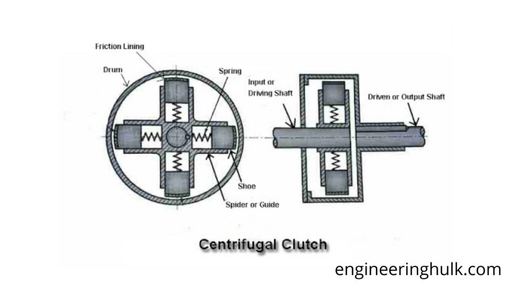
A centrifugal clutch is nothing but an automatic clutch that uses force to function. The output shaft of the clutch disengages at low rotational speed and engages more as speed increases in the centrifugal clutch.
Centrifugal clutch is a non-user-operated device. The centrifugal force provides the axial force required to disengage the clutch. The centrifugal force depends on shaft speed. If the shaft speed is low, the pressure will also be quiet, and the clutch will be disengaged. As shaft speed increases, centrifugal force increases and the clutch becomes “engaged”. As shaft speed gradually increases, the centrifugal force also increases and motion is transferred from the crankshaft to the driven shaft.
The use of a centrifugal clutch on engine-driven equipment allows the engine to start in a no-load situation. When the engine is idle, the transmission remains disengaged. Only when engine RPM is increased to the set clutch engagement speed or higher will the transmission be fully engaged. This leads to a smooth engagement and prevents the engine from stalling. It also helps protect the engine by ensuring high torque levels are not relayed through the engine flywheel.
A centrifugal clutch is usually applied to industrial machines like sweepers, lawnmowers, chainsaws, generator sets, motor pumps, lawnmowers, or fans. They also find applications in refrigeration systems and mini-karts.
Semi Centrifugal Clutch
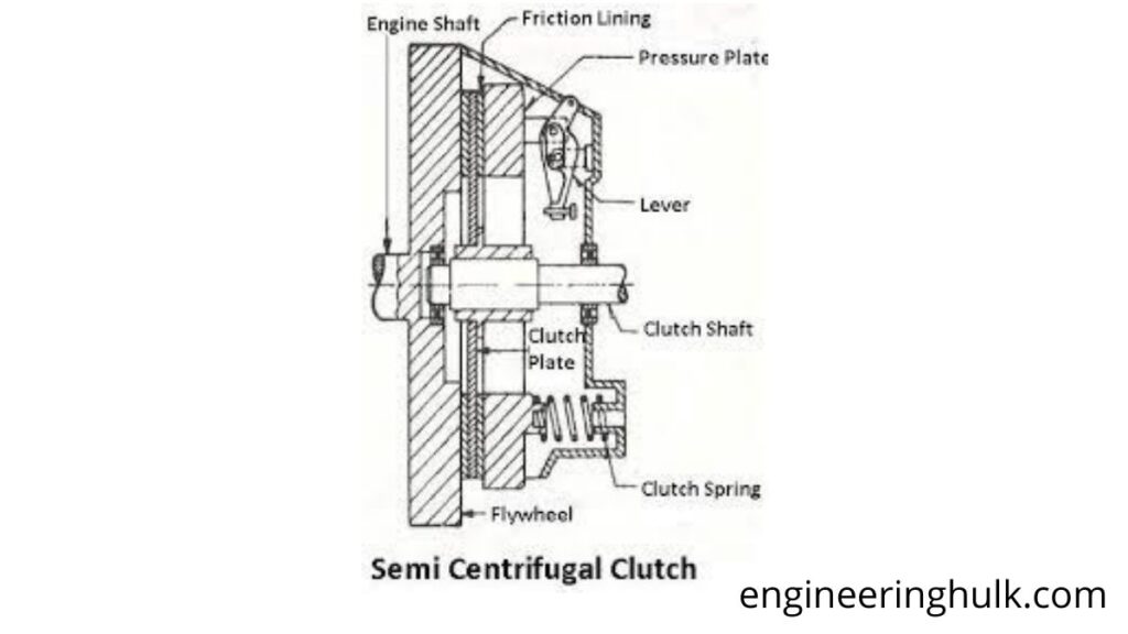
Semi-centrifugal clutches are used in high horsepower engines and racing car engines, where disengaging the clutch requires considerable and tiring driver effort. The power is transmitted in part by the clutch springs and remains from the centrifugal action of an additional weight provided in the system. Clutch springs transmit power at low engine RPM, and centrifugal force transmits power at higher engine RPM.
Semi-centrifugal clutch operation:
When the engine is at low speed, the spring holds the clutch engaged in transmitting power; the heavy levers do not pressure the pressure plate. When the engine is at high speed, the weights fly, and the levers transfer pressure on the pressure plate, which keeps the clutch firmly engaged in transmitting high torque. So, instead of having stiffer springs to keep the clutch firmly engaged at high speeds, they are less rigid due to the centrifugal forces of the ballasted levers, so the driver cannot feel any strain when operating the clutch.
When engine speed decreases, the reactors drop, and ballasted levers put no pressure on the pressure plate, and only spring pressure is exerted on the pressure plate to keep the clutch engaged.
Benefits
• Clutch operation is effortless.
• Less stiff clutch springs are used as they only work at low engine rpm.
Disadvantages
• Springs only transmit torque at lower engine speeds.
• Centrifugal forces act only at higher engine speeds to transmit torque.
Forms
• The semi-centrifugal clutch is used in Vauxhall cars (foreign cars).
Wet Clutch
Definition of wet clutch:
An oil bath clutch transfers power through hydraulic and mechanical couplings, combining rotating friction plates immersed in the lubricant. Wet clutches are typically used in a compact, lubricant-rich environment such as an automatic transmission.
They are called wet because they are immersed in engine oil. The primary purpose of the oil is to cool the clutch plates and, due to this cooling effect, you can abuse the wet clutches a lot, as you would in traffic. In addition, wet clutches usually have a friendly large friction zone, making them very easy to use. They also tend to last a long time and are quieter than dry clutches.
On the other hand, oil bath clutches dirty the engine oil more quickly, as all the dust created during clutch wear remains inside the engine. Fortunately, the oil filter takes care of this. The other disadvantage is that it is more complicated to work with wet clutches. Also, as the clutch spins in the oil, there is fluid resistance that somewhat undermines the engine’s power.
In an oil bath clutch, the friction material is in an oil bath (or has an oil flow), which cools and lubricates the clutch. This can provide smoother engagement and longer clutch life; however, wet clutches may have lower efficiency due to transferring some energy to the oil. Since the surfaces of an oil bath clutch can be slippery (as with a motorcycle clutch soaked in engine oil), stacking multiple clutch plates can compensate. The wet clutch is a variant of the friction clutch. Here, the oil is sprayed onto the plates with the help of the nozzle. They are used in a variety of automobiles.
The friction material used in the clutch plates must have a higher coefficient of friction, and these are drilled so that oil can pass through them. These clutches have an oil inlet. In the lower part, there is a tank to collect the oil from which it is discharged. These clutches have a longer service life than dry clutches due to better heat dissipation and lower coefficient of friction and therefore eliminate slippage under force when fully engaged.
Example: sports bikes
What is a dry clutch?
As the name suggests, a dry clutch is a type of clutch that is not submerged in liquid and uses friction to engage. This type of clutch has its disc on the outside of the motor housing. This means that it is in direct contact with the atmosphere and is not lubricated. Typically, the clutch is more prominent in size to increase the friction plate surface area for optimal air cooling when it overheats due to plate friction. The noise level in the dry clutch is higher than in the wet clutch and continues to increase as the clutch continues to wear.
Example: Ducati
Frequently Asked Questions
What is the function of a clutch in a car?
It connects and disconnects the engine from the gearbox so the vehicle can start from rest smoothly and the driver can change gears.
How does a friction clutch work?
Springs press the clutch plate between the flywheel and pressure plate so friction transmits torque; pressing the pedal moves the pressure plate away and breaks the drive.
What are the main types of clutch?
Single-plate, multi-plate (wet or dry), diaphragm-spring, cone and centrifugal clutches.
What is the difference between a single-plate and multi-plate clutch?
A single-plate clutch has one friction disc and is used in most cars, while a multi-plate clutch has several discs to transmit more torque in a compact space, as in motorcycles and racing cars.
Right here is the right blog for everyone who would like to find out about this topic.
You realize so much its almost hard to argue with you
(not that I personally will need to…HaHa).
You definitely put a new spin on a topic that’s been discussed for many years.
Excellent stuff, just great!
Here is my site 바카라
I couldn’t resist commenting. Perfectly written!
what’s up, principal blog on lardaceous loss. such a one helped.
find