📌 Quick Answer
Steering geometry is the set of angles given to the front wheels and steering linkage, mainly camber, caster, kingpin inclination, toe and the Ackermann angle, that make a vehicle steer easily, run straight and return to centre after a turn.
Correct geometry reduces tyre wear, lowers steering effort and keeps the car stable at speed.
🔹 Key Takeaways
- Camber is the inward or outward tilt of the wheel seen from the front.
- Caster is the forward or backward tilt of the steering axis, which gives self-centring.
- Kingpin inclination and toe affect steering return and straight-line stability.
- The Ackermann principle makes the inner wheel turn more sharply than the outer wheel in a turn.
Steering Geometry Components
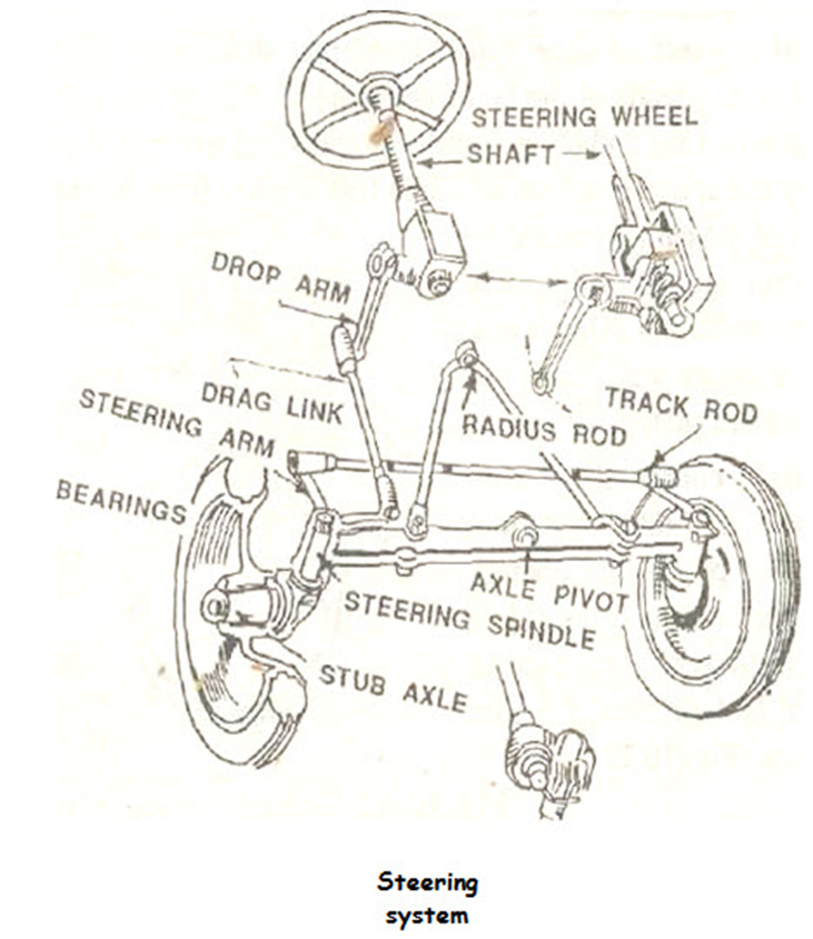
The steering Geometry system can be classified into forwarding steering, rear steering, or integral steering. The system that regulates the angular movement of the front wheels of a vehicle is called the steering system. This flight system minimizes the effort of the operator to turn the front wheel with the application of levers. The different components of the system are:
- steering wheel
- steering shaft
- steering gear
- pitman arm (drop arm)
- drag link
- steering arm
- tie rod
- king pin.
As the operator turns the steering wheel, movement is transmitted through the steering shaft to the angular movement of the tire on the pitman’s arm, via a series of gears. The angular movement of the pitman’s arm is further transmitted to the steering arm through the drag link and tie rods.
The steering arms are coupled to the respective main pins, which are integral parts of the hub of the axle on which the wheels are mounted. The movement of the steering arm affects the angular movement of the front wheel. In another design, instead of a pitman arm and rear links, two pitman arms and rear links are used, and a tie rod is avoided to connect both steering arms.
FRONT AXLE AND STEERING MECHANISM
Front Axle
Front axles are generally dead axles. The front-wheel hubs rotate on an anti-friction tapered roller bearing on the steering pin which is an integral part of the steering knuckle. To allow the wheels to turn from the steering gear, the steering pin and knuckle assemblies are hinged at the end of the axle. The pin that forms the pivot of this hinge is known as the kingpin or steering pin.
FRONT-WHEEL ALIGNMENT
The front wheels must be aligned correctly to ensure smooth steering, provide directional stability to the vehicle, and minimize tire wear. Front-wheel alignment is achieved by precisely setting the following factors:
- Caster
- Camber
- Kingpin inclination
- Toe-in
- Toe-out
CASTER in Steering Geometry
The caster angle is the inclination of the centerline of the pivot or ball joint from the vertical towards the front (negative caster) or the rear (positive caster) of the vehicle.
The angle of attack produces a drag effect and therefore confers directional stability. An incorrect caster can lead to difficulties such as harsh steering, pulling to the side when the brakes are applied. The launch angle varies from negative 2-8 °.

CAMBER in Steering Geometry
The camber angle is the slope between the centerline of the tire and the vertical line. The outward tilt is called the positive sag and the inward tilt is the negative sag. The purpose of the camber is to prevent the wheel tops from tilting too far inward due to excessive load or play on the axle and wheel bearing.
Irregular wheel camber causes vehicles to roll in the direction of a wheel that has the largest camber, which alters directional stability and tends to scratch the tread of the opposite tire, excessive camber prevents the rim from making proper contact with the road, which causes it. to be used only on the side directly under the load.
Camber angle is less than 1 degree

KING-PIN INCLINATION in Steering Geometry
Kingpin inclination is the inward tilt of the kingpin or ball joint centerline from the vertical. Kingpin tilt in combination with curvature provides directional stability. whereas kingpin inclination and camber combine to give direction from the tire’s centre point on the road and bring upthrust at the stub axle closest to the centre of the kingpin. The bending angle combined with the kingpin inclination is called the included angle.
The inclination of the kingpin varies from 4-8°.
TOE-IN in Steering Geometry
The front wheels are usually designed a little forward so that the distance between the rear ends (y) is slightly greater than the distance between the front ends (x). The difference between these distances is called convergence. The wheels are turned inwards to compensate for the tendency to roll outwards due to the curvature and play in the steering linkage.
Convergence is usually 2 to 4 mm.
TOE-OUT in Steering Geometry
When a vehicle turns, the inner wheel of the vehicle moves faster as compared to the outer wheel because the former has to go around an area with a smaller radius than the latter. This action causes the wheels to turn due to differences in their turning angles.
Importance of wheel alignment in Steering Geometry
1. Improve handling: – This helps to control the vehicle. Improper handling can be due to vehicle traction on one side and steering wheel vibration.
2. Improves tire life and performance: – Proper tire contact on the road and prevention of tire slippage due to misalignment results in better tire life.
3. Helps in identifying problems: – Misalignment can be a symptom of something wrong with the vehicle. A check on this can lead to the correction of the vehicle fault.
4. Ensures Safety: – By keeping the system in order, removing defective parts, improves vehicle systems, especially the suspension system, leading to greater safety.
5. Improves fuel efficiency: – By improving the performance of various systems, it leads to better vehicle fuel efficiency.
What is Steering Geometry?
Steering geometry refers to the arrangement and alignment of the wheels and steering components in a vehicle. It ensures that the wheels maintain optimal contact with the road surface, providing stability, control, and efficient handling. Proper steering geometry is essential for reducing tire wear, improving fuel efficiency, and enhancing overall driving comfort.
Key Components of Steering Geometry
- Caster Angle
- Definition: The angle of the steering axis when viewed from the side of the vehicle.
- Impact: Positive caster improves straight-line stability, while negative caster can make steering lighter but less stable.
- SEO Tip: Use keywords like “caster angle in steering geometry” or “how caster affects vehicle handling.”
- Camber Angle
- Definition: The tilt of the wheel when viewed from the front or rear of the vehicle.
- Impact: Proper camber ensures even tire wear and optimal grip during cornering.
- SEO Tip: Include phrases like “camber angle explained” or “effects of camber on tire wear.”
- Toe Angle
- Definition: The difference in distance between the front and rear edges of the tires.
- Impact: Toe-in improves stability, while toe-out enhances cornering response.
- SEO Tip: Use terms like “toe-in vs toe-out” or “how toe angle affects steering.”
- Kingpin Inclination (KPI)
- Definition: The angle between the kingpin and the vertical axis when viewed from the front.
- Impact: KPI reduces steering effort and improves returnability after a turn.
- SEO Tip: Include keywords like “kingpin inclination in steering systems” or “KPI and steering effort.”
- Scrub Radius
- Definition: The distance between the center of the tire contact patch and the point where the steering axis intersects the ground.
- Impact: A smaller scrub radius reduces steering effort and improves stability.
- SEO Tip: Use phrases like “scrub radius explained” or “importance of scrub radius in steering.”
Why is Steering Geometry Important?
- Improved Handling: Proper steering geometry ensures precise control and responsiveness.
- Enhanced Safety: Correct alignment reduces the risk of accidents caused by poor handling.
- Reduced Tire Wear: Optimal geometry prevents uneven tire wear, saving costs in the long run.
- Fuel Efficiency: Proper alignment reduces rolling resistance, improving fuel economy.
Common Steering Geometry Problems and Solutions
- Uneven Tire Wear
- Cause: Incorrect camber or toe settings.
- Solution: Regular wheel alignment checks and adjustments.
- Steering Pull
- Cause: Uneven caster or tire pressure.
- Solution: Balance caster angles and maintain proper tire pressure.
- Vibrations in Steering Wheel
- Cause: Improper alignment or worn-out components.
- Solution: Inspect and replace damaged parts, then realign the wheels.
How to Optimize Steering Geometry for Performance
- Regular Alignment Checks: Ensure your vehicle undergoes alignment checks every 6,000 miles or as recommended by the manufacturer.
- Use Quality Components: Invest in high-quality suspension and steering parts for better performance.
- Consult Experts: Work with automotive engineers or technicians to fine-tune steering geometry for specific driving conditions.
FAQs About Steering Geometry in Automobile Engineering
Q1: What is the ideal caster angle for a car?
A: The ideal caster angle varies by vehicle but typically ranges between 2 to 7 degrees for optimal stability.
Q2: How does steering geometry affect tire wear?
A: Incorrect camber, toe, or caster angles can cause uneven tire wear, reducing tire lifespan.
Q3: Can I adjust steering geometry at home?
A: While minor adjustments can be made, it’s best to consult a professional for precise alignment.
Also, download Mechanical Engineering Books
Frequently Asked Questions
What is steering geometry?
It is the set of wheel and steering-axis angles (camber, caster, kingpin inclination, toe and Ackermann angle) that determine how a vehicle steers and handles.
What is the difference between camber and caster?
Camber is the side-to-side tilt of the wheel viewed from the front, while caster is the front-to-back tilt of the steering axis viewed from the side; caster is what makes the steering self-centre.
What is the Ackermann steering principle?
It is the geometry that makes the inner front wheel turn through a larger angle than the outer wheel during a turn, so both wheels roll about a common centre without scrubbing.
What is toe-in and toe-out?
Toe-in means the front of the wheels point slightly inward; toe-out means they point outward. Correct toe keeps the car tracking straight and reduces tyre wear.
Related Topics on EngineeringHulk
- 👉 Propeller Shafts and Universal Joints
- 👉 Rear Differential – Working & Types
- 👉 Theory of Machines – Study Guide
1 thought on “Steering Geometry in Automobile Engineering”