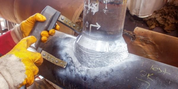
Non-destructive testing (NDT) is a set of inspection methods that find defects in a material, weld or component without damaging it, so the part can go straight back into service. The eight methods used in industry are visual (VT), liquid penetrant (PT), magnetic particle (MT), ultrasonic (UT), radiographic (RT), eddy current (ET), acoustic emission (AE) and infrared thermography (IRT). Each one sees a different kind of flaw, and no single method covers everything, which is why a real inspection plan usually pairs two or three.
What is non-destructive testing and why is it used?
In destructive testing you pull a tensile specimen until it snaps or cut a weld into slices and etch it. You learn a lot, but the specimen is finished and you have only tested a sample. NDT inspects the actual part that will carry load, and the part survives the test.
That difference drives four practical reasons for using it:
- Safety. A boiler drum, an aircraft wing spar or a gas pipeline girth weld cannot be sample-tested. Every joint has to be checked.
- Cost. Finding a lack of fusion while the fabricator still has the job is cheap. Finding it after hydro-testing, painting and erection is not.
- Code compliance. ASME Section VIII, AWS D1.1 and API 1104 all make specific NDT mandatory and name the acceptance limits.
- Life extension. Wall-thickness mapping and crack monitoring tell an operator whether a 25-year-old vessel can run another five years.
NDT does not only look for cracks. It also measures wall thickness, checks coating thickness, sorts alloys and verifies that internal parts of an assembly are in the right place.
Visual testing (VT)
How it works: the inspector looks at the surface, with the eye or through an optical aid. Direct VT uses a mirror, magnifier and torch within about 600 mm of the surface. Remote VT uses a borescope, videoscope, crawler camera or drone to reach the inside of a boiler tube, a turbine casing or a tank roof.
What it finds: surface cracks, undercut, overlap, excess reinforcement, arc strikes, misalignment, surface porosity, corrosion pitting, erosion and missing components. It also catches the things the other methods are not looking for, such as the wrong electrode or a joint left unwelded.
Materials: anything with an accessible surface.
Limits: surface only, and it depends entirely on access, cleanliness, lighting and the inspector’s eyesight. ISO 17637 sets a minimum illuminance of 350 lux on the weld surface, with 500 lux recommended, and requires a certified near-vision check. VT cannot size a defect through the thickness.
Student tip: VT is the first method applied to almost every weld and the cheapest one to get right. A large share of rejects are found here before any equipment is switched on.
Liquid penetrant testing (PT / DPT)
How it works: capillary action. A low-viscosity dye is applied to a clean surface and drawn into any opening that breaks the surface. After a dwell time of roughly 5 to 30 minutes, the excess is removed and a chalky white developer is sprayed on. The developer pulls the trapped dye back out and spreads it, so a hairline crack shows up as a bleeding red line many times wider than the crack itself.
Two versions are common. Visible dye uses red penetrant against white developer in normal light. Fluorescent penetrant is read in a darkened booth under UV-A light at 365 nm and is far more sensitive, which is why aerospace and nuclear work uses it.
What it finds: surface-breaking discontinuities only, but it finds them very well. Fatigue cracks, grinding cracks, quench cracks, laps, seams, cold shuts in castings, and through-wall leak paths.
Materials: any non-porous material. Metals, glass, fired ceramics, many plastics. Its big advantage over magnetic particle testing is that it works on aluminium, copper, titanium and austenitic stainless steel, none of which are magnetic.
Limits: the flaw must be open to the surface and empty. Paint, plating, scale, oil or an earlier smearing operation such as shot blasting can seal the opening and hide the crack. Porous materials such as unfired ceramics and sintered powder-metallurgy parts hold penetrant everywhere and give a useless result. It also generates chemical waste and needs careful pre-cleaning, which is usually the step people skip.
Magnetic particle testing (MT / MPI)
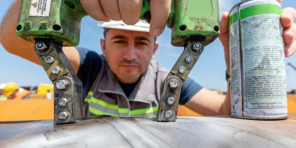
How it works: the part is magnetised, and fine iron oxide particles are dusted or flowed over it. Where a discontinuity interrupts the magnetic flux, some flux leaks out of the surface and forms tiny north and south poles either side of the flaw. The particles are pulled into that leakage field and build a visible indication. Particles come dry or suspended in oil or water, in contrast colours or fluorescent form.
Field is applied with a hand yoke (an AC or DC electromagnet), prods, an encircling coil or a central conductor. Orientation matters: a flaw only shows if it lies roughly 45 to 90 degrees across the flux lines. That is why every MT inspection is done twice, with the field turned through 90 degrees the second time.
What it finds: surface and slightly subsurface flaws, typically down to 2 to 3 mm below the surface, with sensitivity dropping off sharply with depth. Toe cracks, hydrogen cracks, laps, seams, grinding cracks and inclusions.
Materials: ferromagnetic only. Carbon and low-alloy steel, cast iron, ferritic and martensitic stainless steels, and some nickel and cobalt alloys. It will not work on 304 or 316 austenitic stainless, aluminium, copper, brass or titanium.
Limits: the material restriction is the main one. Thick paint reduces sensitivity, the part usually has to be demagnetised afterwards so it does not attract swarf or upset instruments, and prods can leave arc burns on a finished surface.
Ultrasonic testing (UT)
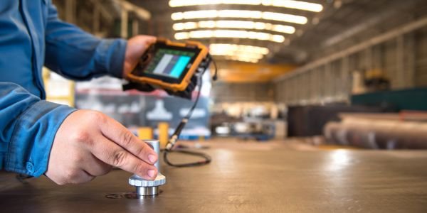
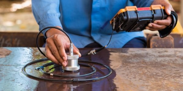
How it works: a piezoelectric crystal sends a short burst of high-frequency sound, usually 0.5 to 15 MHz and most often 2 to 5 MHz for steel, into the part through a couplant of gel, oil or water. The pulse travels until it hits a boundary where the acoustic impedance changes, then part of it reflects. The instrument times that echo. Since longitudinal velocity in steel is about 5,900 m/s, an echo returning in 10 microseconds means a reflector at 5,900 × 10 × 10⁻⁶ ÷ 2, or about 29.5 mm deep. Angle probes use shear waves at roughly 3,230 m/s to reach into a weld from the side.
What it finds: internal flaws at any depth, and planar flaws in particular. Lack of fusion, lack of penetration, cracks, laminations in plate, slag lines and inclusions. It also measures remaining wall thickness on corroded pipe from one side, which no other common method does as quickly.
Materials: most metals, and fine-grained ones best of all. Also works on many plastics and composites with the right probe.
Limits: it needs a trained operator, a couplant and calibration against reference blocks such as the IIW V1 and V2 blocks. Coarse-grained austenitic welds and cast structures scatter the beam badly. There is a dead zone right under the probe, so very thin sections and near-surface flaws are awkward. Rough or curved surfaces reduce coupling, and results depend on how the beam meets the flaw.
Two advanced forms are now standard on critical work. Phased array (PAUT) uses an array of small elements fired with timing delays, so the beam can be steered and focused electronically and the weld is imaged as a sectional view. Time-of-flight diffraction (TOFD) uses a transmitter and receiver either side of the weld and measures the diffracted signals from the tips of a flaw, which sizes the flaw height accurately and is much less sensitive to its orientation. TOFD and PAUT together are widely accepted as a replacement for radiography on pipework and vessels. See this Insight paper on TOFD for the underlying technique.
Radiographic testing (RT)
How it works: penetrating radiation passes through the part onto a detector on the far side. Thinner or less dense regions absorb less radiation, so a void, a gas pore or a slag pocket shows as a darker patch on the radiograph. The source is either an X-ray tube, which can be switched off, or a gamma isotope such as iridium-192 (half-life about 74 days), selenium-75 (about 120 days) or cobalt-60 (about 5.27 years) for thick sections. Image quality indicators are placed on the part to prove the required sensitivity was achieved.
Film is steadily giving way to digital radiography and computed radiography, which give an image in seconds, need no chemicals and can be enhanced and archived.
What it finds: volumetric defects best of all. Porosity, blowholes, slag inclusions, shrinkage cavities in castings, incomplete penetration and wall loss. It also produces a permanent image of internal geometry, which is useful for checking assemblies and for records.
Materials: most materials, with exposure set by thickness and density.
Limits: it is poor at tight planar flaws that lie across the beam. A lack of side-wall fusion barely changes the absorbed dose and can be missed, which is exactly the flaw UT is good at. It needs access to both sides, it is slow, and radiation safety dominates the job: exclusion zones, dose monitoring, licensed sources and trained radiographers. In India, industrial radiography is regulated by the Atomic Energy Regulatory Board, with source licensing and radiological safety officer approvals handled through the e-LORA system, and site radiography is usually done at night with the area cleared.
Eddy current testing (ET)
How it works: an alternating current in a probe coil creates a changing magnetic field, which induces circulating eddy currents in a conductive part underneath. Those currents create their own opposing field, and the coil feels it as a change in impedance. A crack, a corrosion pit or a change in conductivity disturbs the current flow and shifts the impedance, which the instrument plots as a signal on the impedance plane.
Depth of penetration falls as frequency, permeability or conductivity rises, so frequency is the main tuning knob. Low frequency to look deeper, high frequency for fine surface cracks. Practical depth is usually only a few millimetres. The full working principle is covered in this article on eddy current working and applications.
What it finds: surface and near-surface cracks, corrosion thinning, fretting at tube supports, and material property changes. It is the standard method for in-service inspection of heat exchanger and condenser tubing with bobbin probes, and for crack detection around fastener holes on aircraft.
Materials: electrically conductive materials. Non-magnetic conductors such as aluminium, copper, brass and austenitic stainless are the easiest. Ferromagnetic steel can be inspected but the high permeability limits depth and needs magnetic saturation or a related technique.
Limits: no use on plastics, ceramics or concrete. Shallow depth, strong sensitivity to probe lift-off, edges and geometry changes, and signals that take real training to read. Its compensating advantages are that it is fast, needs no couplant and works through thin paint.
Acoustic emission testing (AE)
How it works: AE is passive. Instead of sending energy in, sensors listen for the ultrasonic stress waves, typically 100 kHz to 1 MHz, that a material releases on its own when a crack grows, a fibre breaks, a bolt slips or a plate yields. The structure has to be under load, so AE is normally run during a hydrotest, a pressure ramp or normal service. Several sensors are bonded to the outside and the source is located by comparing arrival times, the same way a seismic network locates an earthquake.
What it finds: only active defects. A crack that is growing under load emits; a dormant crack of the same size stays silent. AE tells you where something is moving and how active it is, not how big it is.
Materials: metals, composites, concrete, fibre-reinforced pressure vessels and rock.
Limits: background noise from pumps, flow, rain and friction is the constant enemy, and interpretation is specialised. Because it gives activity and rough position rather than size, AE is used as a screening tool over a whole vessel, storage tank or bridge in a single test, after which UT or RT is sent to the flagged spots for sizing. It is also the only common method that can monitor a structure continuously while it works.
Infrared thermography (IRT)
How it works: an infrared camera maps surface temperature. In passive thermography the item is already hot or cold from its own operation, so you photograph an electrical panel, a furnace lining, a steam trap or a building wall and look for anomalies. In active thermography you inject a heat pulse with a flash lamp, hot air or induction and film how the surface cools. A delamination or void below the surface blocks heat flow into the part, so the skin above it stays hotter for longer and appears as a bright patch.
What it finds: delaminations and disbonds in composites, water ingress in honeycomb panels, corrosion under insulation, refractory damage, loose or overheating electrical connections, blocked tubes and missing insulation.
Materials: composites, coated metals, insulation, concrete and electrical assemblies.
Limits: shallow. Active thermography typically resolves flaws only a few millimetres deep, and depth resolution falls fast as flaw depth grows. Readings are upset by surface emissivity differences, reflections from hot objects nearby, wind and sunlight. It is excellent for covering a large area quickly, weak at precise sizing.
NDT method selection table
| Method | Surface or subsurface | Typical defects found | Suitable materials | Main limitation |
|---|---|---|---|---|
| Visual (VT) | Surface | Cracks, undercut, misalignment, corrosion, weld profile faults | All | Surface only; needs access and 350 lux minimum |
| Liquid penetrant (PT) | Surface-breaking only | Fatigue and grinding cracks, laps, seams, cold shuts, leaks | Any non-porous material, magnetic or not | Flaw must be open and clean; no porous materials |
| Magnetic particle (MT) | Surface and up to about 3 mm deep | Toe and hydrogen cracks, laps, seams, near-surface inclusions | Ferromagnetic only: carbon steel, cast iron, ferritic stainless | No aluminium, copper, titanium or austenitic stainless |
| Ultrasonic (UT) | Full thickness | Lack of fusion, lack of penetration, cracks, laminations, wall loss | Most metals, best in fine-grained material | Needs couplant, calibration and a skilled operator |
| Radiographic (RT) | Full thickness | Porosity, slag, shrinkage, incomplete penetration | Most materials | Radiation hazard; misses tight planar flaws across the beam |
| Eddy current (ET) | Surface and near-surface, a few mm | Cracks, pitting, tube wall loss, conductivity and alloy sorting | Conductive materials only | Shallow; sensitive to lift-off and geometry |
| Acoustic emission (AE) | Whole structure, active flaws | Growing cracks, fibre breakage, leaks, yielding | Metals, composites, concrete | Needs load; gives activity and location, not size |
| Thermography (IRT) | Surface to a few mm | Delamination, disbond, corrosion under insulation, hot joints | Composites, coated metals, insulation, electricals | Shallow; emissivity and reflection errors |
A quick way to choose. Is the flaw open to the surface? PT covers any material, MT is faster and more sensitive but only on steel. Is it buried? UT for planar flaws and thickness, RT for volumetric flaws and a permanent image. Tubing or aircraft skin? ET. A whole vessel to screen in one shot? AE. A large composite panel or a live switchboard? IRT. And VT before all of them.
Where NDT is used
- Welding and fabrication: VT on every weld, then MT or PT on the surface and UT or RT for the root and body of the joint.
- Power and process plant: boiler tube thickness by UT, header and pipe welds by RT or PAUT, turbine blade roots by PT, condenser tubes by ET.
- Oil and gas: girth welds by automated UT, corrosion mapping, tank floors by magnetic flux leakage, in-line inspection pigs.
- Aerospace: fluorescent PT and ET on metal structure, thermography and UT on composite skins.
- Railways: ultrasonic flaw detection of rails and axles is routine in India, with trolley-mounted and car-mounted USFD systems.
- Foundry and automotive: castings and forgings checked by RT and MT, gear and shaft cracks by PT.
NDT standards and certification levels
NDT results are only meaningful if the person doing the test is qualified and the procedure follows a recognised standard. Two certification routes dominate.
ASNT SNT-TC-1A is a recommended practice from the American Society for Nondestructive Testing. It is employer-based: each employer writes its own Written Practice using SNT-TC-1A as the guideline, then trains, examines and certifies its own people. Certification belongs to the employer and does not automatically transfer when the technician changes jobs. ANSI/ASNT CP-189 is the stricter national standard version of the same idea, and the ASNT NDT Level III examination is administered centrally by ASNT.
ISO 9712 is the international alternative and works differently. It is third-party certification issued by an independent certification body accredited to ISO/IEC 17024, after central examinations. Because the certificate is not tied to one employer, it travels with the technician, which is why it is the usual requirement on European and Gulf projects.
Both schemes use the same three levels:
| Level | What the holder may do |
|---|---|
| Level I | Carry out the test to a written instruction, set up equipment as directed and record results. Does not evaluate or accept the part independently. |
| Level II | Set up and calibrate equipment, interpret and evaluate indications against the applicable code, write instructions for Level I, and report results. This is the working inspector grade. |
| Level III | Write and approve procedures, select the method and technique, interpret codes and standards, and train and examine Level I and II personnel. |
A trainee works under supervision until certified. Vision checks, documented training hours and documented on-the-job experience are required at every level, and the hours differ by method. The ASNT website publishes the current requirements, which are revised periodically, so always check the edition your employer or client calls up rather than an old table.
Method and product standards you will meet alongside the personnel schemes: ASME Boiler and Pressure Vessel Code Section V for the test methods themselves, ASME Section VIII and Section IX, AWS D1.1 for structural steel welds, API 1104 for pipeline welds, ISO 17635 for weld NDT selection, and ASTM E1417 (PT), E1444 (MT), E94 (RT) and E114 (UT).
NDT in India
The Indian Society for Non-Destructive Testing (ISNT) is the national professional body and India’s member of the International Committee for NDT. It runs training courses, conferences and a certification scheme, and most Indian employers write their Written Practice around SNT-TC-1A while larger EPC contractors and export-oriented shops also ask for ISO 9712.
Indian Standards cover the individual methods, including IS 2595 for radiographic testing of fusion-welded joints, IS 3658 for liquid penetrant flaw detection, IS 3664 for ultrasonic pulse-echo testing and IS 3703 for magnetic particle flaw detection.
On the research and nuclear side, BARC in Mumbai and IGCAR at Kalpakkam carry out advanced NDT development and in-house qualification of personnel for nuclear components, including work on phased array, thermography and remote inspection of reactor internals. Anyone handling radioactive sources for industrial radiography needs AERB licensing, which is a separate requirement from NDT method certification.
Advantages and limitations of NDT overall
| Advantages | Limitations |
|---|---|
| The tested part stays usable, so 100 percent inspection is possible | Results depend heavily on operator skill and interpretation |
| Can be repeated on the same part over its life to track a flaw | Most methods are indirect, so indications need judgement |
| Works in the field, on erected and in-service equipment | Capital cost of PAUT, digital RT and AE systems is high |
| Finds problems early, cutting rework and failure cost | No single method covers surface and volumetric flaws together |
| Supports code compliance and gives a documented record | Radiography brings radiation hazard and site downtime |
References
- American Society for Nondestructive Testing (ASNT) – certification schemes and method overviews.
- Time-of-flight diffraction (TOFD), Insight, BINDT.
- ASME Boiler and Pressure Vessel Code, Section V – Nondestructive Examination.
- ISO 9712, Non-destructive testing – Qualification and certification of NDT personnel.
FAQs
What is non-destructive testing (NDT)?
Non-destructive testing is inspection that detects defects in a material or component without damaging it, so the part can still be used afterwards. The main methods are visual, liquid penetrant, magnetic particle, ultrasonic, radiographic, eddy current, acoustic emission and thermography.
What are the main types of NDT methods?
Eight methods cover almost all industrial work: visual (VT), liquid penetrant (PT), magnetic particle (MT), ultrasonic (UT), radiographic (RT), eddy current (ET), acoustic emission (AE) and infrared thermography (IRT). VT, PT, MT, ET and IRT find surface or near-surface flaws, while UT and RT reach through the full thickness.
Which NDT method detects internal defects?
Ultrasonic testing and radiographic testing are the two that see through the full thickness. UT is better for planar flaws such as lack of fusion and cracks, and it also measures remaining wall thickness. RT is better for volumetric flaws such as porosity, slag and shrinkage cavities, and it leaves a permanent image.
What is the difference between magnetic particle and liquid penetrant testing?
Magnetic particle testing works only on ferromagnetic materials such as carbon steel and cast iron, and it can find flaws a few millimetres below the surface. Liquid penetrant works on any non-porous material, including aluminium and austenitic stainless steel, but only finds flaws that break the surface.
What are NDT Level I, II and III?
Level I performs tests to written instructions and records results. Level II calibrates equipment, interprets indications and evaluates them against the code. Level III writes and approves procedures and trains and examines other personnel. Levels are awarded under employer-based ASNT SNT-TC-1A or third-party ISO 9712 certification.