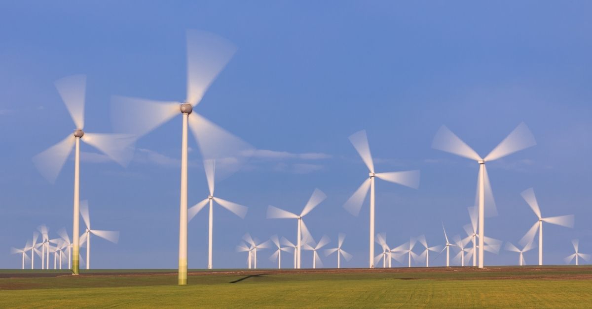
A wind turbine blade is a long, twisted aerofoil. The air meets each blade section at a relative wind made up of the wind speed and the blade’s own rotational speed, and the section produces a lift force at right angles to that relative wind and a drag force along it. Resolving lift and drag in the plane of rotation gives the torque that turns the rotor; resolving them along the wind direction gives the thrust that bends the blades and pushes on the tower. Modern turbines are lift-driven, and blade aerodynamics is about keeping every section at the angle that gives high lift and low drag.
Lift and drag on a blade section
Cut a blade across its span and the cross-section is an aerofoil: rounded leading edge, sharp trailing edge, usually cambered. The straight line from leading to trailing edge is the chord, c. Air speeds up over the curved upper (suction) side and pressure there falls, while pressure on the lower side is higher. That pressure difference, plus skin friction, gives a resultant force, split into two parts:
- Lift, L, perpendicular to the relative wind: L = ½ ρ W² c CL per metre of span
- Drag, D, parallel to the relative wind: D = ½ ρ W² c CD per metre of span
Here ρ is air density (1.225 kg/m3 at sea level, 15 °C), W is the relative wind speed at that section, and CL and CD are the lift and drag coefficients. Both coefficients depend on the angle of attack, α, the angle between the chord and the relative wind. Lift rises roughly in proportion to α until the flow separates from the upper surface, the section stalls, lift drops and drag climbs sharply. Wind turbine aerofoils are designed for a high lift-to-drag ratio (L/D) just below the stall angle.
Relative wind: the blade velocity triangle
A blade section at radius r does not see the free wind. It sees the vector sum of two velocities:
- the axial wind arriving at the rotor, v(1 – a), which is a little slower than the free wind v because the rotor slows the air (a is the axial induction factor), and
- the tangential velocity of the section moving through the air, Ωr, where Ω is the rotor speed in rad/s.
The relative wind is W = √[(v(1 – a))² + (Ωr)²], and it meets the rotor plane at the inflow angle φ, where tan φ = v(1 – a) / (Ωr). Near the tip, Ωr is many times the wind speed, so W is almost in the plane of rotation and φ is small.
Angle of attack, pitch and twist: why blades are twisted
The inflow angle φ is shared between two angles:
φ = α + θ, where θ is the local blade angle (the blade pitch setting plus the twist at that section).
Tangential speed Ωr grows with radius, so φ is large near the hub and small near the tip. To hold every section near its best angle of attack, θ must also be large at the root and small at the tip. That is why a wind turbine blade is visibly twisted along its length. The chord also shrinks towards the tip, because a fast-moving outer section needs less area to produce the same lift. The pitch system turns the whole blade about its long axis to change θ everywhere at once, which is how the turbine controls power.
Lift-based vs drag-based rotors
A drag-based rotor, such as a cup anemometer or a Savonius rotor, is pushed by the wind like a sail running downwind. Its surfaces can never move faster than the wind, so it captures little energy. A lift-based rotor, such as a modern three-blade horizontal axis turbine or a Darrieus rotor, has blades moving across the wind, with tips several times faster than the wind itself. Lift acts across the relative wind, so it produces useful torque at high rotor speeds. All utility-scale turbines are lift-based. Our page on horizontal and vertical axis wind machines compares the two layouts.
Power in the wind and the Betz limit
The kinetic energy flowing through the rotor’s swept area A each second is:
P = ½ ρ A v³
A rotor cannot extract all of it, because the air must keep moving to leave the rotor. Betz’s analysis shows the maximum power coefficient is Cp,max = 16/27 = 0.593. Real rotors lose more to drag, tip losses and wake rotation; large modern turbines reach roughly 70 to 80% of the Betz limit, a Cp of about 0.41 to 0.47.
Worked example 1: power from a 100 m rotor
Rotor diameter 100 m, wind speed 10 m/s, ρ = 1.225 kg/m3.
- Swept area A = π × 50² = 7854 m2.
- Power in the wind = 0.5 × 1.225 × 7854 × 10³ = 4,810,000 W = 4.81 MW.
- Betz maximum = 0.593 × 4.81 = 2.85 MW.
- With a realistic Cp = 0.45: 0.45 × 4.81 = 2.16 MW at the rotor shaft, before gearbox and generator losses.
Because power goes with v³, the same rotor at 8 m/s has only (8/10)³ = 0.51 of this power. Wind speed at the site matters more than anything else.
Tip speed ratio
The tip speed ratio compares blade tip speed with wind speed:
λ = ΩR / v
Cp depends strongly on λ. Too slow, and wind passes between the blades unused; too fast, and the rotor behaves like a solid disc and drag losses rise. High-efficiency three-blade turbines run at tip speed ratios of about 6 to 7, and variable-speed turbines change rotor speed with the wind to stay near that value.
Worked example 2: rotor speed
For the 100 m rotor (R = 50 m) at v = 10 m/s and λ = 7:
- Ω = λv / R = 7 × 10 / 50 = 1.4 rad/s.
- In rpm: 1.4 × 60 / (2π) = 13.4 rpm.
- Tip speed = ΩR = 1.4 × 50 = 70 m/s, seven times the wind speed.
Thrust and torque from lift and drag
Lift and drag are defined relative to W, but the turbine cares about two other directions: along the rotor axis (thrust) and in the plane of rotation (torque). Resolving with the inflow angle φ, per metre of span:
- Normal (thrust) force: FN = L cos φ + D sin φ
- Tangential (driving) force: FT = L sin φ – D cos φ
Only a small part of lift, L sin φ, drives the rotor, because φ is small. Drag works against it. Most of the lift becomes thrust.
Worked example 3: forces on one blade section
Take the rotor above (Ω = 1.4 rad/s, v = 10 m/s) and a section at r = 35 m with chord 2 m. Assume the ideal axial induction a = 1/3, and illustrative aerofoil values CL = 1.0 and CD = 0.01 (L/D = 100) at α = 5°. Tangential induction is ignored to keep it simple.
- Tangential speed Ωr = 1.4 × 35 = 49 m/s. Axial speed v(1 – a) = 10 × 2/3 = 6.67 m/s.
- Relative wind W = √(6.67² + 49²) = 49.45 m/s.
- Inflow angle φ = tan-1(6.67 / 49) = 7.75°. With α = 5°, the local blade angle θ = 7.75 – 5 = 2.75°.
- Dynamic pressure ½ρW² = 0.5 × 1.225 × 49.45² = 1498 Pa.
- Lift L = 1498 × 2 × 1.0 = 2996 N/m; drag D = 1498 × 2 × 0.01 = 30 N/m.
- Thrust force FN = 2996 cos 7.75° + 30 sin 7.75° = 2972 N/m.
- Driving force FT = 2996 sin 7.75° – 30 cos 7.75° = 404 – 30 = 374 N/m.
- Torque from this metre of blade = 374 × 35 = about 13,100 N·m per metre of span.
Two lessons come out of the numbers. First, the thrust on the section is about eight times the driving force, which is why towers and blade roots are designed for thrust. Second, even with L/D as high as 100, drag cuts the driving force by about 7% (from 404 to 374 N/m), because it acts almost directly against rotation. That is why blade designers chase a high lift-to-drag ratio.
Blade element momentum (BEM) theory in words
The worked example assumed a = 1/3. In a real design the induction factors are unknown and differ along the blade. Blade element momentum theory finds them:
- Divide the blade into many short elements (annular rings of the rotor disc).
- For each element, guess the axial and tangential induction factors.
- From the velocity triangle, find W, φ and α, read CL and CD from aerofoil data, and work out the thrust and torque on the element (blade element theory).
- Separately, work out the thrust and torque the same ring must produce to slow the air by that amount (momentum theory).
- Adjust the induction factors until both answers agree, then add corrections for tip and hub losses.
- Sum all elements to get the rotor’s thrust, torque, power and Cp.
BEM is quick and remains the standard method for blade design and load calculation, with CFD used for detailed checks.
Stall control vs pitch control
Above the rated wind speed, the turbine must shed extra power to protect the generator.
- Stall control (passive): blades are fixed to the hub at a set angle. As wind speed rises, φ and α increase until outer sections stall, lift falls and power levels off. Simple, but it cannot hold a constant output over a wide wind range, and the stalled blades carry high loads. Mostly found on older and small turbines.
- Pitch control (active): the blades are turned about their long axis, typically within about 0 to 30 degrees, to reduce α and hold power at the rated value. Feathering the blades also stops the rotor in storms. Almost all large modern turbines use pitch control with variable speed.
Why most turbines have three blades
Going from one blade to two raises efficiency by about 6%, and from two to three by about 3% more; a fourth blade adds little and costs a full blade of material. Three blades also balance the cyclic loads at the shaft, so the rotor runs smoothly when the nacelle yaws, which a two-blade rotor does not. Three is the compromise between energy capture, smooth running and cost.
Wind power in India
According to the Ministry of New and Renewable Energy (MNRE), India’s installed wind power capacity was 58,520 MW (about 58.5 GW) as on 31 August 2026. Gujarat and Tamil Nadu have the largest shares, followed by Karnataka, Maharashtra and Rajasthan (state figures as of February 2026). The US Department of Energy has a plain explainer on how wind turbines work, and the history of traditional windmills is on Wikipedia.
FAQs
What forces act on a wind turbine blade?
Lift, perpendicular to the relative wind, and drag, along it. Resolved into the rotor’s directions, they give a tangential force that produces torque and a normal force that produces thrust on the rotor and tower. Blades also carry gravity and centrifugal loads.
Why are wind turbine blades twisted?
The blade’s speed increases with radius, so the relative wind meets the root at a steep angle and the tip at a shallow one. Twist sets each section at the angle of attack that gives the best lift-to-drag ratio.
What is the Betz limit?
It is the maximum fraction of the wind’s kinetic energy an ideal rotor can extract: 16/27, or 59.3%. Real large turbines reach a power coefficient of roughly 0.41 to 0.47.
What is the tip speed ratio of a wind turbine?
It is blade tip speed divided by wind speed, λ = ΩR / v. Efficient three-blade turbines run at about 6 to 7.
Is a modern wind turbine lift-based or drag-based?
Lift-based. Drag-based rotors such as the Savonius cannot move faster than the wind and capture far less energy, so they are used only for small, simple machines.