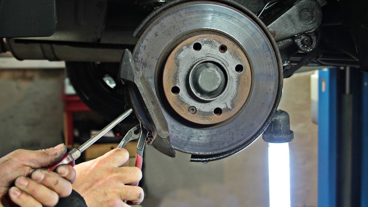
A good automobile brake system must stop the vehicle in the shortest safe distance, keep it straight and steerable while doing so, hold it stationary on a slope, and keep working when hot, wet or partly failed, all with a reasonable pedal effort. In design terms, the requirements are: high deceleration and short stopping distance, resistance to fade, good heat dissipation, equal braking on both sides, anti-skid behaviour, a parking brake that holds on a gradient, reliability through dual circuits, low and progressive pedal effort, and long life with little maintenance. Each is explained below with the numbers behind it.
This page covers what brakes must achieve. How the hardware achieves it is covered in the companion articles on the hydraulic brake system, mechanical brakes, the master cylinder and the antilock braking system (ABS).
Requirements of a brake system at a glance
| Requirement | What it means | How designers meet it |
|---|---|---|
| Short stopping distance | High, controllable deceleration | Enough brake torque at every wheel; good tyres |
| Fade resistance | Braking force stays the same when brakes are hot | Friction materials with stable μ; discs rather than drums |
| Heat dissipation | Kinetic energy removed as heat without overheating | Disc mass, ventilated discs, airflow |
| Equal braking | Same force on left and right wheels of an axle | Symmetric design, correct adjustment |
| Correct front/rear distribution | Rear wheels do not lock before the front | Proportioning or load-sensing valves, electronic brake-force distribution |
| Anti-skid | Wheels keep rolling so the driver can steer | ABS |
| Parking hold | Vehicle stays put on a slope with no driver | Mechanical or electric parking brake, independent of hydraulics |
| Reliability and redundancy | Some braking remains after one failure | Dual (split) circuits, tandem master cylinder, warning lamp |
| Low, progressive pedal effort | Deceleration proportional to pedal force, without excessive force | Pedal leverage, hydraulic advantage, vacuum servo |
| Durability and low maintenance | Long lining life, little noise, easy service | Wear-resistant linings, self-adjusters, wear indicators |
1. Short stopping distance and high deceleration
The first requirement is to stop quickly. Total stopping distance has two parts:
- Reaction (thinking) distance = v × tr, covered at full speed while the driver sees the hazard and moves to the pedal. Road designers in India commonly assume a perception-reaction time of 2.5 s; an alert driver may manage about 1 s.
- Braking distance = v² / (2a), covered while the brakes decelerate the vehicle at a.
The maximum deceleration is limited by tyre grip: amax = μ × g, where μ is the tyre-road friction coefficient (roughly 0.7 to 0.8 on dry asphalt, much lower when wet). The brakes must be strong enough to reach this limit at every wheel; beyond it, extra brake force only locks the wheels. That is why tyres are as much part of braking as the brakes themselves.
Worked example: stopping distance at 72 km/h
Problem: a car travels at 72 km/h on a dry road with μ = 0.7. The driver’s reaction time is 1.0 s. Find the total stopping distance, and repeat for 100 km/h.
- Speed: 72 km/h = 72 / 3.6 = 20 m/s.
- Reaction distance = 20 × 1.0 = 20 m.
- Deceleration a = μg = 0.7 × 9.81 = 6.87 m/s².
- Braking distance = v² / (2a) = 20² / (2 × 6.87) = 400 / 13.73 = 29.1 m.
- Total stopping distance = 20 + 29.1 = 49.1 m.
At 100 km/h (27.8 m/s): reaction distance = 27.8 m, braking distance = 27.8² / 13.73 = 56.2 m, total = 84.0 m. Speed rose by 39%, but braking distance nearly doubled, because it grows with the square of speed. With a 2.5 s reaction time, the reaction distance alone at 100 km/h would be 69 m. The equations used are the standard kinematic equations for constant deceleration.
Type-approval tests set minimum performance. For example, UN Regulation No. 13-H, used in many countries for passenger cars, requires a laden car braking from 100 km/h to stop within 0.1v + 0.0060v² = 10 + 60 = 70 m (v in km/h), with a pedal force no higher than 500 N. That formula already includes an allowance for system response time.
2. Fade resistance
Brake fade is a loss of braking force when the brakes get hot, typically during repeated hard stops or a long downhill run. The friction coefficient of the lining falls at high temperature, so the same pedal force gives less deceleration. A good brake system must keep its friction nearly constant over its working temperature range. Designers meet this with friction materials chosen for stable μ when hot (see friction materials) and with disc brakes, which fade less than drums because the disc is exposed to air and does not expand away from the lining. Water fade (a wet lining) and vapour lock (boiling brake fluid) are separate faults; the difference is explained in the hydraulic brake article.
3. Heat dissipation: where the energy goes
Friction brakes stop a vehicle by turning its kinetic energy into heat. The brake must absorb that heat and get rid of it before the next stop.
Worked example: temperature rise of a brake disc
Problem: a 1,200 kg car stops from 72 km/h (20 m/s). The front brakes take 70% of the braking. Each front disc has a mass of 6 kg and is grey cast iron with specific heat c = 460 J/kg·K. Estimate the temperature rise of each front disc for one stop, assuming all the heat goes into the discs.
- Kinetic energy = ½mv² = 0.5 × 1,200 × 20² = 240,000 J (240 kJ).
- Energy to the front axle = 0.70 × 240 = 168 kJ, so each front disc gets 84 kJ.
- Temperature rise ΔT = Q / (m c) = 84,000 / (6 × 460) = 30.4 °C.
From 100 km/h the energy is 463 kJ, and the same calculation gives about 59 °C per disc per stop. The stop at 6.87 m/s² from 20 m/s takes 20 / 6.87 = 2.9 s, so the average braking power is 240 / 2.9 = about 82 kW, comparable to the full power of a small car engine.
One stop is easy to absorb. The problem is repetition: stop after stop, or a long descent on a ghat road, adds heat faster than the disc can shed it, and the temperature climbs towards the point where fade starts. That is why front discs are often ventilated (two plates joined by vanes that pump air through), why heavy vehicles use exhaust brakes or retarders on descents, and why drivers are told to use a lower gear downhill. The figures here are simplified: in reality some heat goes into the pads and hub, and the disc starts cooling during the stop.
4. Equal braking and correct front/rear distribution
The wheels on each axle must brake equally. If the left front brake is stronger than the right, the car pulls to the left under braking. Causes in service are uneven adjustment, a seized caliper or oil on one lining.
Between the axles, the force must suit the load. Braking shifts weight forward, so the front wheels can carry more braking force than the rear; in a typical car the front brakes do roughly two-thirds or more of the work. If the rear wheels lock first, the back of the car loses sideways grip and it can spin. If the front wheels lock first, the car goes straight on and cannot be steered, which is easier to recover but still dangerous. Designers therefore bias the brakes to the front and use proportioning valves, load-sensing valves or electronic brake-force distribution so the rear never locks first. Stability under braking links to handling behaviour described in oversteer and understeer.
5. Anti-skid: keep the wheels rolling
A locked tyre slides with less grip than a rolling one near its peak, and a sliding front tyre cannot steer. The ideal brake keeps each wheel just short of locking. That is the job of the antilock braking system, which senses a wheel about to lock and releases and reapplies pressure many times per second, so the driver can brake hard and steer at the same time. In India, rules under the Central Motor Vehicles Rules require ABS or combined braking on new two-wheelers depending on engine size; the hydraulic brake article covers these rules.
6. Parking brake: holding on a gradient
The parking brake must hold a laden vehicle on a slope without the driver, and it must work mechanically (or electrically), independent of the hydraulic service brake. UN Regulation 13-H, for example, requires a car’s parking brake to hold it laden on a 20% gradient, up or down.
Example: a 1,200 kg car on a 20% (1 in 5) gradient. The angle is tan-1(0.20) = 11.3° and sin 11.3° = 0.196. The force pulling the car downhill = mg sinθ = 1,200 × 9.81 × 0.196 = 2,309 N. If the parking brake acts on two rear wheels of 0.30 m rolling radius, the total brake torque needed = 2,309 × 0.30 = 693 N·m, or about 346 N·m per wheel, before any safety margin.
7. Reliability and redundancy
Brakes must work every time, and a single failure must not leave the driver with none. The main features:
- Dual (split) hydraulic circuits fed by a tandem master cylinder, split front/rear or diagonally, so a leak in one circuit leaves the other working.
- A secondary (emergency) braking capability, which the regulations test separately.
- Warning lamps for low fluid and pad wear.
- On trucks and buses with air brakes, spring brakes that apply automatically if air pressure is lost.
How the split circuit and tandem master cylinder work is explained in the master cylinder article.
8. Low and progressive pedal effort
The driver must be able to reach full braking without excessive force, and deceleration should rise smoothly in proportion to pedal force so it can be judged. Too light and the brakes feel grabby; too heavy and weaker drivers cannot stop hard in an emergency. Pedal leverage, the hydraulic ratio between master cylinder and wheel cylinders, and a vacuum servo together multiply the driver’s effort; the hydraulic brake article works through the force multiplication. The brakes must also release fully and quickly when the pedal is let go, without drag.
9. Durability, low maintenance and other practical needs
- Linings with long wear life and little dust, and asbestos-free materials.
- Little noise (squeal) and judder.
- Automatic adjustment for lining wear, and easy inspection and replacement.
- Resistance to water, mud and corrosion.
- Low weight, since brake parts are unsprung mass on most vehicles.
Brake types used to meet these requirements
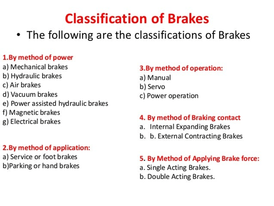
No single brake type meets every requirement, so vehicles combine them: hydraulic disc brakes at the front for fade resistance and heat dissipation, discs or drums at the rear, a mechanical parking brake, and air brakes on heavy vehicles. In India, the performance and test requirements for vehicle brakes are set out in the IS 11852 series from the Bureau of Indian Standards, which has separate parts for general functions, performance requirements, test procedures, air and vacuum brakes, and vehicles with ABS, alongside the Automotive Industry Standards used for type approval. For lectures on vehicle dynamics and braking, see NPTEL.
FAQs
What are the main requirements of a brake system?
It must stop the vehicle in a short distance, keep it stable and steerable, resist fade, dissipate heat, brake equally on both sides, prevent wheel lock, hold the vehicle on a slope, stay partly working after a failure, and need only a reasonable pedal effort.
How is stopping distance calculated?
Stopping distance = reaction distance + braking distance = v × tr + v² / (2μg). At 72 km/h (20 m/s) with a 1 s reaction time and μ = 0.7, it is 20 + 29.1 = 49.1 m.
What is brake fade?
Brake fade is the loss of braking force when brakes overheat, usually from repeated hard stops or long descents, because the lining’s friction coefficient drops at high temperature. Disc brakes and heat-stable friction materials reduce it.
Why should the front wheels not lock before the rear, or vice versa?
If the rear wheels lock first, the vehicle can spin. If the front wheels lock first, it cannot be steered. Brakes are biased to the front and controlled by proportioning valves or ABS so the rear never locks first and ideally neither axle locks.
Why do vehicles have dual brake circuits?
So that a leak or failure in one hydraulic circuit leaves the other circuit working, giving the driver reduced but still usable braking instead of none.