📌 Quick Answer
A propeller shaft (drive shaft) transmits rotary power from the gearbox output to the final drive at the rear axle, and universal joints at its ends let it transmit that power even as the angle between the gearbox and axle changes.
Because the rear axle moves up and down on its suspension, the shaft also needs a slip (splined) joint to allow its length to change, and universal joints to accommodate the changing drive angle.
🔹 Key Takeaways
- The propeller shaft carries drive from the gearbox to the rear final drive.
- Universal (Hooke’s) joints allow drive through a varying angle.
- A slip joint allows the effective length of the shaft to change with suspension movement.
- Two universal joints (in phase) are used to cancel the speed fluctuation of a single joint.
Propeller shaft:
Movement from the gearbox is transferred to the differential which is the next component of the transmission system. The differential is located in the center of the rear axle and the vehicle is rear-wheel drive. Alternatively, the vehicle can be a front-wheel-drive, or, in some cases, engine motion can be transferred to both the front and rear axles.
In the case of a rear-wheel-drive vehicle, the distance between the gearbox and the differential can be considerable and the driveshaft connecting the two has a considerable length. In the case of front-wheel drive, the distance between the two could be small, and therefore a small driveshaft would be needed. To study the driveshaft it is worth considering a rear-wheel-drive vehicle.

Functions of the propeller shaft:
In most motor vehicles, the engine is located at the front and the rear wheels of the vehicle are powered. This arrangement requires the use of a longer drive shaft. In some configurations, two or three drive shafts are used to compensate for the length. The propeller shaft is the post that transmits gearbox control to the differential rigging in a motor vehicle from the engine to the propeller in a boat or flying machine.
REQUIREMENTS OF PROPELLER SHAFT:
To realize production capabilities, the next ones are normal in a driveshaft
- High torsional quality: therefore they are made with a sturdy or hollow round cross-segment
- Hardened and Solidified: Therefore, they are made of prevailing quality steel and are solidified for enrollment
- Joint efficiently: so they are mostly welded by submerged carbon dioxide welding process.
- Dynamic Tuning: As the spinning wonder could be crucial at higher rates, prop shafts are tested on the electronic tuning machine as a result.
- Reduced thrust loads: reverberation is risky for the life of the tree. It also transmits excessive unique power to the pole’s terminal supports, so its event should be kept at a strategic distance.
TYPES OF PROPELLER SHAFT:
1. One-piece propeller shaft:
• Used in vehicles with a short distance between the engine and axles and MR-based four-wheel drive vehicles.
• The friction welding used at the joint helps to improve the strength, quality and durability of the joint.
2. 2 Piece / 3 Piece Propeller Shaft:
1. Used as part of vehicles with a long distance between the engine and axles and four-wheel drive vehicles with front engine front drive base.
2. Splitting the propeller shaft into two or three parts reduces the critical RPM, preventing vibration problems from occurring when the overall shaft length is increased.
3. Universal Joints: (Coupling Hooks)
Robert Hooke is commonly known as the inventor of the “Hooke Joint” or “Universal Joint”. There are various names used for universal joints such as universal joint, U joint, gimbal, Spicer joint, or Hardy Spicer joint.
Universal joints are mainly used to create flexible connections between two rigid angled shafts. Allows for constantly variable power transmission. It is used to connect the driveshaft with the shift shaft to transmit rotary motion.
Power transmission under varying conditions is impossible without the use of a flexible device or gimbal. This flexible device is also used in vehicles having coupling shafts between the clutch and gearbox, between the main gearbox and auxiliary gearbox, and also on the drive shafts of the driven front axle.
TYPES OF UNIVERSAL JOINT
- Variable speed couplings
• Cross or spider type
• Type of ringtone
• Ball and trunnion type
2. Constant speed couplings (CV)
• Rzeppa
• Bendix Weiss
• Treated
1. Variable speed couplings
In this case, both the driven shaft and the crankshaft do not rotate at the same speed even though each part of a revolution is at the same number of revolutions. The driven and motor shafts must be positioned in a straight line to turn at the same speed through each part of a revolution. But in practice, it won’t be feasible in any car. The crankshaft is always inclined.
If there is an angle between the driven shaft and the crankshaft, the driven shaft will be less than the crankshaft by half a turn and faster than the crankshaft for the other half turn. Hence, the average speed of the driven shaft equals the crankshaft. The speed variation in the driven shaft increases as the bending angle of the universal joint increases.
If two variable speed universal pairs are used in two transmission lines, the yoke on the shaft connected to the universal pairs must not be indifferent planes. Provides balance to changes in speed.
Variable Velocity Joints are following These Types
- Cross or spider type
- Ring type
- Ball and trunnion type
Cross or Spider Type:
In universal joints, the two yokes where one is connected to the drive shaft, and the other is connected perpendicular to the driven shaft to the shaft driven by a cross or spider. Needle bearings are mounted between the yokes and the transverse ends. These types of couplings are generally used in crankshafts.
Ring Type:
This type of joint uses a flexible ring. The rod has two or three armed spiders. The arms are bolted to opposite faces of the flexible ring. The arms of one spider are placed halfway between the arms of the other. The flexible ring consists of one or more rubber rings to provide sufficient strength
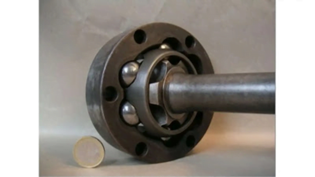
Ball and pin type:
This type uses a combination of universal and sliding joints in a single assembly. A pin or cross shaft is connected transversely in a “T” shape to the end of a shaft of the gimbal. A ball is mounted on needle roller bearings at each end of the cross shaft. The complete unit slides freely in the grooves made in the external body of the joint. The heavy spring resists excessive longitudinal movement of the shaft.
Power is transmitted through the pin, balls and cross shaft. Bending moment occurs by rolling the ball in one direction. It is also in the opposite direction by moving the balls longitudinally in the grooves of the pin. The open end of the shaft is covered by leather or rubber boot covers.
2. Constant Velocity joints
In this type of joint, the driven shaft is rotated at the same speed that the drive shaft rotates through each part of the revolution at any degree of deflection. These couplings are mainly used in the front drive axles to transmit power over large angles. Cadillac cars use ball and socket-type CV joints in their drive shafts.
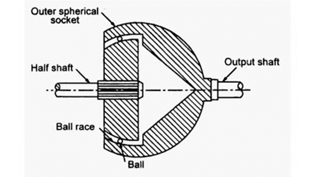
Rzeppa :
It consists of internal and external spherical races in which the grooves are cut parallel to the shaft. The steel balls are placed in the grooves on the spherical races. Torque transmission occurs from one stroke to the other ball. The circular pattern of the spheres causes the shafts to rotate at the same speed.
Bendix Weiss:
In this type of articulation, the principle of crossing spheres arranged in a circle around a sphere is used. Four numbers of drive balls are placed in tracks machined in tight-fitting yokes. A central fifth ball is held between two yokes as an inside run. The guide balls are arranged in a circle in the same way as the Rzeppa joint. The ball alignment action provides a Constant Velocity joint.
Tracta :

This joint differs from the two previous joints. Four yokes are used in this joint where two yokes are attached to the shafts and the other two are floating in the center of the joint. The mating parts of the yokes are transformed into segments of a circle. Both the circular segments and the floating action of the two yokes provide a constant velocity joint.

WORKING OF UNIVERSAL JOINT
- In the case of an automobile, the gearbox is rigidly mounted. Due to the action of the road springs, the position of the rear axle is constantly varied and tolerance is provided if the gearbox is mounted on the rear axle via a driveshaft.
- A gimbal consists of two yokes. These yokes are attached to each end of the shaft. The two yokes are joined by a central or connecting crosspiece. The connecting cross member will turn the yoke bearings as the angularity between the shafts changes. They do not transmit motion evenly if the trees run at an angle.
- Materials used for universal joints
- Universal joints can be made from almost any material depending on the application.
- Common materials used include stainless steel, steel, naval brass, and other similar alloys to handle higher torques and temperatures.
APPLICATIONS OF UNIVERSAL JOINT
- Universal joints vary according to the composition of the material, the type of hub, and the applications for which they are designed, it is a positive mechanical joint that is used to connect the shafts.
- The universal joint is most commonly found in the driveshaft of rear-wheel drive cars.
- Specific applications of universal joints include aircraft, appliances, control systems, electronics, instrumentation, textile machinery, medical and optical equipment, radios, weapons, sewing machines, and tool drives.
Advantages of Universal Joint
1. The universal coupling is more flexible than the swivel joint.
2. Facilitates torque transmission between angular misaligned shafts.
3. It is economical and convenient.
4. It is simple to assemble and disassemble.
5. The efficiency of torque transmission is high.
6. The joint allows angular displacements.
Disadvantages of Universal Joint
1. Wear can occur if the coupling is not properly lubricated.
2. Maintenance is often required to avoid wear.
3. The universal joint produces a floating motion
4. Does not support axial misalignment.
FAQ
What is a propeller shaft?
A propeller shaft, also known as a drive shaft or prop shaft, is a mechanical component used to transmit torque from the engine to the wheels or other driven components in a vehicle or machinery.
What is the purpose of a universal joint?
A universal joint, or U-joint, is a flexible coupling that allows for the transmission of torque between two shafts that are not in a straight line. It accommodates misalignment and changes in the angle between the shafts.
How does a universal joint work?
A universal joint consists of two yokes connected by a cross-shaped bearing or spider. The spider allows the yokes to pivot and transmit torque even when the shafts are at different angles. It typically contains needle bearings for smooth rotation.
Where are propeller shafts commonly used?
Propeller shafts are commonly found in rear-wheel drive vehicles, as they transmit torque from the transmission or transfer case to the rear axle. They are also used in industrial applications such as marine propulsion systems and heavy machinery.
What are the different types of universal joints?
There are several types of universal joints, including the cross-and-bearing type (most common in automotive applications), constant velocity (CV) joints, and double-cardan joints. Each type has its own advantages and limitations.
What are the signs of a failing universal joint?
Some signs of a failing universal joint include vibration or shaking during acceleration, clunking noises from the drivetrain, and difficulty shifting gears. Excessive play or movement in the joint is also an indication of potential failure.
How can I maintain a propeller shaft and universal joints?
Regular maintenance involves inspecting the joints for wear, ensuring proper lubrication, and replacing damaged or worn components. It is also essential to address any drivetrain vibrations promptly, as they can lead to accelerated wear on the universal joints.
Can universal joints be replaced individually?
Yes, in many cases, universal joints can be replaced individually. However, it is generally recommended to replace all the joints in a propeller shaft at the same time to ensure even wear and optimal performance.
Are there any alternatives to universal joints?
Yes, there are alternative flexible couplings used for torque transmission, such as CV joints, which are often used in front-wheel drive vehicles. Some applications may also utilize flexible couplings like flexible disc couplings or constant velocity shafts.
Can propeller shafts and universal joints be modified or customized?
Yes, propeller shafts and universal joints can be modified or customized to suit specific applications. Specialized materials, lengths, or configurations can be designed and manufactured to meet the requirements of unique setups or machinery.
References
- Society of Automotive Engineers (SAE) International: SAE publishes technical papers and standards related to automotive engineering, including topics such as propeller shafts and universal joints. Their publications can be found on the SAE Digital Library (www.sae.org).
- Automotive Handbook by Robert Bosch GmbH: This comprehensive handbook covers various aspects of automotive engineering, including drivetrain components like propeller shafts and universal joints. It is widely used as a reference in the automotive industry.
- Machinery’s Handbook by Erik Oberg et al.: This well-known reference book for mechanical engineering covers a wide range of topics, including power transmission systems. It provides valuable information on universal joints and their applications.
- Automotive Transmissions: Fundamentals, Selection, Design and Application by Harald Naunheimer et al.: This book focuses specifically on automotive transmissions, including propeller shafts and universal joints. It offers in-depth technical information and design considerations.
- Mechanical Engineering Design by Joseph Edward Shigley et al.: This textbook covers the fundamental principles of mechanical engineering design. It includes a section on power transmission systems that discusses propeller shafts and universal joints.
Frequently Asked Questions
What is the function of a propeller shaft?
It transmits the engine’s drive from the gearbox to the rear axle’s final drive while allowing for the angle and length changes caused by suspension movement.
Why are universal joints used in a propeller shaft?
Because the rear axle moves relative to the gearbox, the drive angle keeps changing; universal joints let the shaft keep transmitting torque through that changing angle.
Why does a propeller shaft use two universal joints?
A single Hooke’s joint makes the output speed fluctuate within each revolution. Using two joints in the correct phase cancels this fluctuation so the axle turns at a steady speed.
What is a slip joint on a drive shaft?
It is a splined sliding joint that lets the shaft lengthen and shorten as the rear axle moves up and down, preventing the drive line from binding.
Related Topics on EngineeringHulk
- 👉 Rear Differential – Construction & Working
- 👉 Synchromesh Gear Box
- 👉 Gear Trains – Theory of Machines Study Guide
Thank you so much for your comment. I appreciate
If you don”t mind proceed with this extraordinary work and I anticipate a greater amount of your magnificent blog entries
Very nice article, I enjoyed reading your post, very nice share, I want to twit this to my followers. Thanks!.
Cool stuff you have and you keep overhaul every one of us
Thanks for posting this info. I just want to let you know that I just check out your site and I find it very interesting and informative. I can’t wait to read lots of your posts.
Al-Ahliyya Amman University
AAU Started providing academic services in 1990, Al-Ahliyya Amman University (AAU) was the first private university and pioneer of private education in Jordan. AAU has been accorded institutional and programmatic accreditation. It is a member of the International Association of Universities, Federation of the Universities of the Islamic World, Union of Arab Universities and Association of Arab Private Institutions of Higher Education. AAU always seeks distinction by upgrading learning outcomes through the adoption of methods and strategies that depend on a system of quality control and effective follow-up at all its faculties, departments, centers and administrative units. The overall aim is to become a flagship university not only at the Hashemite Kingdom of Jordan level but also at the Arab World level. In this vein, AAU has adopted Information Technology as an essential ingredient in its activities, especially e-learning, and it has incorporated it in its educational processes in all fields of specialization to become the first such university to do so.
I have read so many posts about the blogger lovers however this post is really a good piece of writing, keep it up
whoah this blog is wonderful i really like reading your articles. Keep up the great paintings! You realize, a lot of people are hunting round for this info, you could help them greatly.
https://www.philadelphia.edu.jo/library/directors-message-library