 EngineeringHulk
- Home
- Blog
- Automobile Engineering
- Dynamo in Automobile Engineering: Construction, Working, Control Box and Dynamo vs Alternator
Dynamo in Automobile Engineering: Construction, Working, Control Box and Dynamo vs Alternator
On this page
An automobile dynamo is a belt-driven DC generator that charged the battery and powered the electrics of cars built up to the 1960s. It uses a commutator and brushes to turn the AC induced in its rotating armature into direct current, and a separate control box to regulate it. A typical British car dynamo such as the Lucas C40 gave only about 20 to 22 A. From 1960 onward the alternator, which produces far more current, including at idle, gradually replaced it, and by the late 1960s alternators were fitted to nearly all new cars.

What is an automotive dynamo?
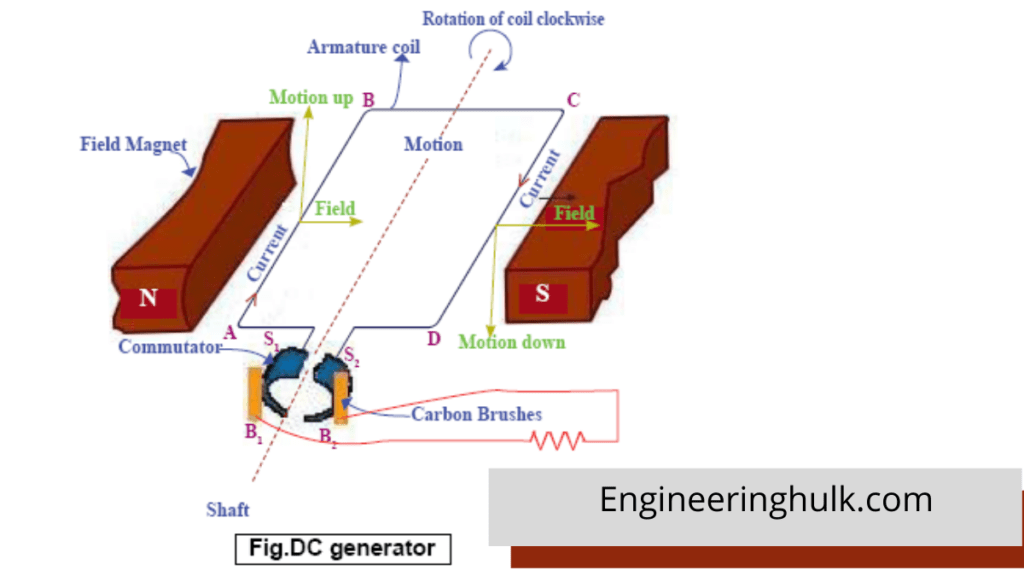
In automobile engineering, “dynamo” means a shunt-wound DC generator mounted on the engine and driven from the crankshaft pulley by the fan belt. Its field coils are connected in parallel (shunt) with the armature and are fed from the dynamo’s own output, so the machine excites itself from the small residual magnetism left in the poles. It works on Faraday’s law of electromagnetic induction: conductors moving through a magnetic field have an EMF induced in them.
The dynamo has two jobs: recharge the battery after starting, and supply lights, ignition and accessories when the engine is running above idle.
Construction of a car dynamo (parts for the diagram)
If you are drawing a diagram of a dynamo, these are the parts to label, working from the outside in:
| Part | Material and form | Function |
|---|---|---|
| Yoke (body) | Cylindrical steel shell | Holds the poles and carries the magnetic flux between them; also the outer casing |
| Field poles (pole shoes) | Soft iron pieces screwed inside the yoke, usually two | Shape and concentrate the magnetic field across the armature |
| Field coils | Many turns of fine copper wire wound round the poles | Produce the magnetic field; current through them is controlled by the regulator |
| Armature | Laminated iron core on a shaft, with copper windings in slots | Rotates in the field; EMF is induced in its conductors |
| Commutator | Copper segments insulated by mica, at one end of the armature | Reverses the armature connections every half turn, so the output is DC |
| Brushes | Carbon blocks pressed by springs onto the commutator | Collect current from the rotating commutator |
| End brackets and bearings | Commutator-end bracket (bush) and drive-end bracket (ball bearing) | Support the armature shaft |
| Pulley and fan | On the drive end of the shaft | Belt drive from the crankshaft; the fan cools the windings |
| Terminals | Two: D (dynamo output) and F (field) | Connect to the control box |
How the dynamo works
- The engine turns the armature through the fan belt.
- Armature conductors cut the magnetic field between the poles, and an alternating EMF is induced in each coil.
- As each coil’s EMF reverses, the commutator segment it is connected to moves to the other brush. The brushes therefore always see the EMF in the same direction: the output is DC, with a small ripple.
- Part of the output flows back through the field coils. As speed rises, output rises, the field strengthens and output rises further. Left alone, voltage would climb far too high, so a control box limits it.
Worked example: generated EMF
The EMF of a DC generator is
E = P φ Z N / (60 A)
where P = number of poles, φ = flux per pole (Wb), Z = total armature conductors, N = speed (rpm) and A = number of parallel paths (A = 2 for a wave winding, and for any winding on a two-pole machine).
Take an illustrative two-pole car dynamo with P = 2, A = 2, Z = 280 conductors and φ = 1.5 mWb at full field, turning at N = 2,000 rpm:
E = (2 × 0.0015 × 280 × 2,000) / (60 × 2) = 1,680 / 120 = 14.0 V
That is enough to charge a 12 V battery. Now suppose the dynamo pulley makes it turn at 1.75 times engine speed, and the engine idles at 800 rpm. The dynamo turns at 1,400 rpm, and since E is proportional to N at a given flux:
E = 14.0 × 1,400 / 2,000 = 9.8 V
This is below battery voltage, so the dynamo cannot charge at idle. To reach a typical cut-in voltage of about 13 V it must turn at 2,000 × 13 / 14 ≈ 1,860 rpm. This single calculation shows the dynamo’s main weakness. (The numbers are illustrative; real dynamo constants vary.)
The control box: cut-out, voltage regulator and current regulator
A dynamo needs external control. On most cars this sat in a separate control box with electromagnetic relays; the fuller version had three units.
1. Cut-out (reverse-current relay)
At low speed the dynamo voltage is below the battery’s, and without protection the battery would discharge back through the dynamo, trying to drive it as a motor. The cut-out is a relay with a voltage coil and a current coil. It closes its contacts to connect the dynamo to the battery only when dynamo voltage rises above battery voltage, and opens them when the dynamo slows and current starts to flow backwards. A Rootes (Hillman) workshop manual gives settings for the Lucas system of cut-in at 12.7 to 13.3 V, drop-off at 8.5 to 11.0 V, and a reverse current of 3.5 to 5.0 A to open the contacts.
2. Voltage regulator
A vibrating-contact relay in the field circuit. When output voltage reaches its setting, the contacts open and put a resistance in series with the field, weakening it and lowering the output. The contacts vibrate many times a second, holding the average voltage steady. The setting is temperature-compensated: the same manual quotes an open-circuit setting falling from 16.1 to 16.7 V at 10 °C to 15.0 to 15.6 V at 40 °C, because a cold battery needs a higher charging voltage.
3. Current regulator
A similar vibrating relay with a series (current) coil. It weakens the field when output current reaches the dynamo’s maximum rating, protecting the armature from overheating when the battery is flat and a heavy load is switched on. Simpler two-unit control boxes left this job to a compensating winding on the voltage regulator.
Today the equivalent functions are handled by the diodes and the electronic regulator built into the alternator, with no mechanical contacts.
Why the alternator replaced the dynamo
Chrysler fitted an alternator as standard on the 1960 Valiant, several years ahead of Ford and General Motors. As cheap silicon diodes made rectifying AC practical, other makers followed through the 1960s, and since the late 1960s alternators have replaced dynamos in nearly all automotive use. The reasons:
- Low output at idle. As the worked example shows, a dynamo gives little or nothing at idle. It cannot be geared up much, because its heavy armature and commutator cannot tolerate high speeds. An alternator can be run faster and gives useful charge at idle, which matters in traffic with lights, wipers and heater running.
- Commutator and brush wear. The dynamo’s brushes carry the full output current across a segmented commutator, so they spark and wear. An alternator’s brushes carry only the small field current to smooth slip rings, and last far longer.
- Output for its weight. A C40 dynamo gave about 20 to 22 A. Typical car alternators are rated around 50 to 70 A, and often more, from a similar or smaller, lighter unit.
- Simpler control. Diodes block reverse current automatically, so no cut-out is needed, and the alternator limits its own maximum current, so no current regulator is needed.
- Rising electrical loads. Heated windows, radios, stronger headlamps and later electronic ignition and fuel injection needed more current than dynamos could supply.
Dynamo vs alternator
| Point | Dynamo | Alternator |
|---|---|---|
| What it generates | DC, via a commutator | Three-phase AC, rectified to DC by diodes |
| Rotating part | Armature (carries the output current) | Field (rotor) with a small excitation current |
| Stationary part | Field poles and coils | Three-phase stator windings (carry the output current) |
| Brushes run on | Segmented commutator, full output current | Smooth slip rings, field current only |
| Charging at idle | Little or none | Useful charge |
| Typical car output | Around 20 A (Lucas C40: 20 to 22 A) | About 50 to 70 A in older and smaller cars, often more today |
| Maximum speed | Limited by commutator and armature | High; can be geared to run faster |
| Reverse-current protection | Cut-out relay in control box | Built into the rectifier diodes |
| Regulation | External electromechanical control box | Electronic regulator, usually built in |
| Maintenance | Brushes and commutator need regular attention | Brushes last much longer; little routine service |
| Era | Standard until the 1960s | Standard since the late 1960s |
For how the modern system works, see our page on the alternator in automobiles, and for what it charges, the lead-acid battery in automobiles.
Where dynamos survive today
- Classic and vintage cars, motorcycles and tractors still run original dynamos. Owners often fit an electronic regulator in the old control box, or a “dynamo-look” alternator hidden in a dynamo-shaped case for more output.
- Bicycle “dynamos” are a naming quirk. The bottle and hub dynamos on bicycles are almost always small permanent-magnet alternators that produce AC. Most modern hub dynamos are regulated to 3 W at 6 V.
- Teaching labs: DC generator experiments in B.Tech electrical machines labs use the same principle and the same EMF equation.
For the underlying physics, see the NCERT Class 12 Physics chapter on electromagnetic induction.
FAQs
What does dynamo mean in an automobile?
It is the belt-driven DC generator that charged the battery and supplied the electrical system on older vehicles. It produces direct current using a commutator and brushes, controlled by a separate cut-out and regulator box.
What is the main difference between a dynamo and an alternator?
A dynamo generates DC directly using a commutator, with the output coming from the rotating armature. An alternator generates AC in a stationary stator and converts it to DC with diodes. The alternator gives more current, charges at idle and needs less maintenance.
Why does a dynamo not charge at idle?
Generated voltage is proportional to speed. At idle the dynamo turns too slowly for its voltage to exceed battery voltage, so the cut-out stays open and no charging current flows.
What is the function of the cut-out in a dynamo system?
It connects the dynamo to the battery only when dynamo voltage is higher than battery voltage and disconnects it when it falls, so the battery cannot discharge back through the dynamo.
Is a bicycle dynamo really a dynamo?
Usually not. Bicycle hub and bottle “dynamos” are small permanent-magnet AC generators, that is, alternators. The name stuck from earlier usage.
Related Topics on EngineeringHulk
Keep reading
Alternator in Automobile Engineering: Parts, Working, Voltage Regulation and Testing
How a car alternator works: claw-pole rotor, stator, diode rectifier and regulator, output vs speed, a pulley and belt-load worked example, and testing.

Starting System in Automobile Engineering: Components, Circuit and Working
How the engine starting (cranking) system works: battery, switches, relay, solenoid, series-wound starter motor, drive types, a worked example and faults.
Wheels and Tyres in Automobile Engineering: Difference, Types, Construction and Tyre Size
Difference between wheel and tyre, wheel types, rim terms, tyre construction, radial vs bias ply, and how to read a tyre size like 185/65 R15 88H.
Differential in Automobile Engineering: Rear Differential Working, Parts and Types
How a rear differential works: why the outer wheel travels farther in a turn, crown wheel and pinion, planet gears, types compared, gear ratio and upkeep.
Lead Acid Battery in Automobiles: Construction, Working and Types
Lead acid battery construction explained part by part: plates, grids, separators, electrolyte, cell chemistry, SMF/AGM/EFB types, ratings and a worked example.

Bendix Drive in a Starter Motor: Working, Construction and Modern Alternatives
How a Bendix drive engages and throws out the starter pinion, its parts and failure modes, plus inertia vs pre-engaged starter drives compared.