📌 Quick Answer
An alternator is the engine-driven generator that produces electricity to charge the battery and run the vehicle’s electrical systems while the engine is running.
It generates alternating current (AC) in its stator windings as the rotor’s magnetic field spins, then a set of diodes rectifies it to DC for the battery.
🔹 Key Takeaways
- The alternator charges the battery and powers electrical loads while the engine runs.
- It is belt-driven by the engine crankshaft.
- Construction: a rotating field (rotor), stationary windings (stator), diodes, and a voltage regulator.
- It produces AC, which diodes rectify into the DC the car needs.
- The voltage regulator keeps output steady (~13.5-14.5 V) regardless of engine speed.
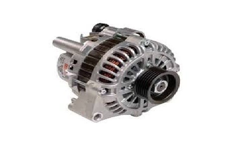
What Is an Alternator?
The alternator is the heart of the vehicle’s charging system. Driven by a belt from the engine, it generates the electricity that recharges the battery and powers everything from the ignition to the lights while the engine runs.
Construction and Working
An alternator has a rotor (an electromagnet spun by the drive belt), a stator (fixed three-phase windings), a rectifier (diode bridge), and a voltage regulator. As the rotor’s magnetic field rotates inside the stator, it induces alternating current in the windings. The diode rectifier converts this AC to DC, and the regulator holds the output around 13.5-14.5 V so the battery charges correctly at any engine speed.
Frequently Asked Questions
What is the function of an alternator?
To generate electricity that charges the battery and powers the vehicle’s electrical systems while the engine is running.
Why does an alternator produce AC but the car uses DC?
The spinning magnetic field naturally induces alternating current in the stator windings; a diode rectifier then converts that AC to the DC the battery and electrical system require.
What keeps the alternator’s output voltage steady?
A voltage regulator adjusts the rotor’s field current so the output stays around 13.5-14.5 V regardless of engine speed or electrical load.
Related Topics on EngineeringHulk
- 👉 https://engineeringhulk.com/battery-charging-methods-in-automobiles/
- 👉 https://engineeringhulk.com/lead-acid-battery-in-automobiles/
- 👉 https://engineeringhulk.com/starting-system-in-automobile-engineering/
1 thought on “Alternator in Automobile Engineering”