
The main components of an IC engine are the cylinder block, cylinder head, crankcase, piston with piston rings, gudgeon pin, connecting rod, crankshaft, flywheel, camshaft and valves. The stationary parts form the combustion space and hold everything in line; the moving parts turn the push of burning gas on the piston into rotation of the crankshaft. Around them sit the fuel, ignition, cooling, lubrication and starting systems.
The table below lists the internal combustion engine components with what each one does and what it is usually made of. The sections after it take the parts in groups: stationary, moving, then the systems. For the thermodynamic cycles these parts carry out, see our Otto cycle and Diesel cycle page.
Main parts of an IC engine at a glance
| Component | Function | Typical material |
|---|---|---|
| Cylinder block | Main body; contains the cylinders, coolant passages and crankshaft bearings | Grey cast iron or aluminium alloy |
| Cylinder liner | Replaceable wear surface the piston slides in | Centrifugally cast iron (alloyed) |
| Cylinder head | Closes the top of the cylinder; holds valves, ports and spark plug or injector | Aluminium alloy or cast iron |
| Head gasket | Seals head to block against gas, coolant and oil | Multi-layer steel (MLS) or composite |
| Crankcase | Houses and supports the crankshaft | Cast iron or aluminium (often part of the block) |
| Oil sump | Stores lubricating oil below the crankshaft | Pressed steel or cast aluminium |
| Inlet and exhaust manifolds | Carry fresh charge in and burnt gas out | Inlet: aluminium or glass-filled nylon; exhaust: cast iron or stainless steel |
| Piston | Receives gas pressure and transmits it to the connecting rod | Aluminium alloy; steel or composite crowns on heavy diesels |
| Piston rings | Seal the gas (compression rings) and scrape oil (oil control ring) | Cast iron or steel, often chrome-plated |
| Gudgeon pin | Pivot joining piston to connecting rod | Case-hardened alloy steel |
| Connecting rod | Links piston to crankshaft; converts reciprocating to rotary motion | Forged steel (sintered or cast in some mass-market engines) |
| Crankshaft | Turns the connecting rod’s push into output torque | Forged steel or SG (nodular) cast iron |
| Flywheel | Stores energy to smooth out speed between power strokes | Cast iron or steel |
| Camshaft | Opens the valves at the right time | Chilled cast iron or forged steel |
| Valves | Open and close the inlet and exhaust ports | Inlet: silicon-chromium steel; exhaust: austenitic heat-resisting steel |
| Spark plug / fuel injector | Starts combustion (petrol) or sprays fuel into hot air (diesel) | Ceramic insulator with nickel or iridium electrodes / hardened steel nozzle |
Stationary components of an IC engine
Cylinder block
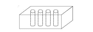
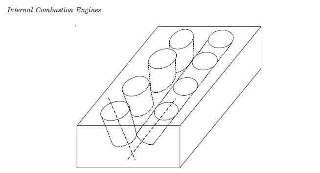
The cylinder block is the backbone of the engine. It contains the cylinder bores, the water jackets through which coolant flows, oil galleries, and the main bearing housings for the crankshaft. Almost every other part bolts to it. Older and heavy-duty engines use grey cast iron because it is cheap, damps vibration and wears well. Most modern car engines use aluminium alloy blocks to save weight, with cast-iron liners or a hard coating in the bores.
Cylinder liners: wet and dry
A liner (or sleeve) is a separate tube pressed or slipped into the block so that the worn surface can be replaced without scrapping the whole block.
- Dry liner: a thin sleeve pressed into the bore. Coolant never touches it; heat passes through the block wall. Simple, no sealing problem, but slower heat transfer.
- Wet liner: a thicker sleeve whose outer surface forms one wall of the water jacket, so coolant touches it directly. It cools better and is easy to replace, but needs rubber sealing rings at the bottom to stop coolant leaking into the sump. Common in trucks, tractors and large diesels.
Cylinder head
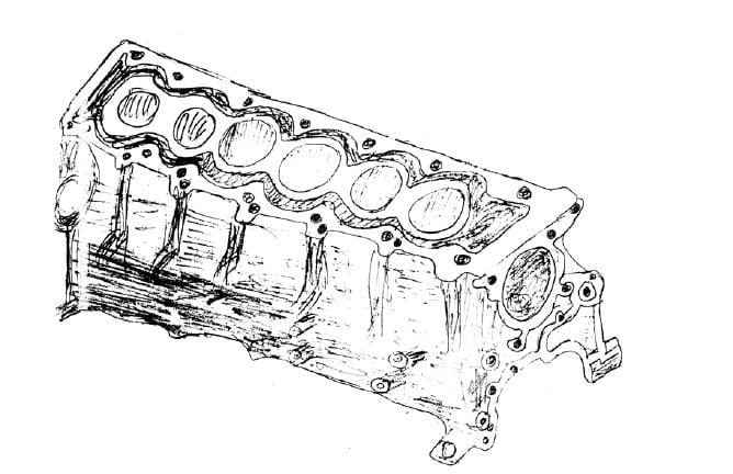
The cylinder head closes the top of each cylinder and forms most of the combustion chamber. It carries the inlet and exhaust ports, the valves with their guides and seats, the spark plug or injector, and in most modern engines the camshaft as well. Aluminium alloy heads are the norm in cars because aluminium conducts heat away from the chamber quickly.
Crankcase, gaskets, oil sump and manifolds
- Crankcase: the lower part of the engine that encloses the crankshaft. In most car engines it is cast in one piece with the block.
- Gaskets: the head gasket seals the joint between head and block against combustion pressure, coolant and oil at the same time. Smaller gaskets seal the sump, covers and manifolds.
- Oil sump: the pan bolted under the crankcase. It holds the engine oil, which the oil pump draws up through a strainer.
- Inlet manifold: distributes air (or air-fuel mixture) to each cylinder.
- Exhaust manifold: collects hot exhaust gas from each cylinder and sends it to the exhaust pipe, catalytic converter or turbocharger.
Moving components of an IC engine
Piston
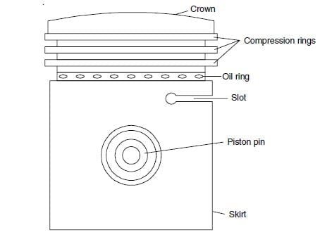
The piston is a cup-shaped plug that slides up and down in the cylinder. On the power stroke, gas pressure acting on its crown pushes it down; on the other strokes it draws in, compresses and pushes out the charge. It must be light (it reverses direction twice every revolution) and must carry heat from the crown to the rings and cylinder wall. That is why aluminium alloy is the usual choice.
Piston rings: compression and oil control
A car piston usually carries three rings in grooves near the top:
- Top compression ring: seals the combustion gas and passes heat to the cylinder wall.
- Second ring: backs up the gas seal and helps scrape oil down.
- Oil control ring: the lowest ring, slotted or made of rails with a spring expander. It wipes surplus oil off the cylinder wall and returns it to the sump through holes in the piston, so oil does not reach the combustion chamber and burn.
Worn rings show up as low compression, blue exhaust smoke and high oil consumption.
Gudgeon pin
The gudgeon pin (piston pin or wrist pin) is a hollow hardened steel pin that passes through the piston bosses and the small end of the connecting rod. It lets the rod swing as the crank turns. A fully floating pin is free in both the piston and the rod and is held by circlips.
Connecting rod
The connecting rod joins the piston to the crankshaft. Its small end takes the gudgeon pin; its big end, split into two halves with bolts and lined with shell bearings, wraps round the crankpin. The rod is usually an I-section forging, which gives a high stiffness for its weight. Together with the crank it converts the piston’s straight-line motion into rotation.
Crankshaft
The crankshaft is the output shaft. It has main journals that turn in the main bearings, crankpins offset from the axis by half the stroke, and webs with counterweights that balance the rotating mass. Power from each cylinder arrives at its crankpin in turn, and the shaft delivers the combined torque to the flywheel and clutch. Crankshafts are forged steel in high-output and diesel engines, and SG iron in many petrol engines.

Flywheel
A four-stroke cylinder gives only one power stroke every two revolutions, so crankshaft speed would rise and fall sharply without a store of energy. The flywheel is a heavy disc bolted to the rear of the crankshaft. It absorbs energy during the power stroke and gives it back during the other three strokes. It also carries the ring gear that the starter motor turns and the friction face for the clutch.
Camshaft, valves and valve train
Each cylinder of a four-stroke engine has at least one inlet and one exhaust valve. These are poppet valves: a disc-shaped head on a stem, held shut against its seat by a spring. The camshaft carries one egg-shaped cam per valve; as it turns, each cam lobe pushes its valve open and then lets the spring close it. The camshaft turns at half crankshaft speed, because each valve opens once every two revolutions.
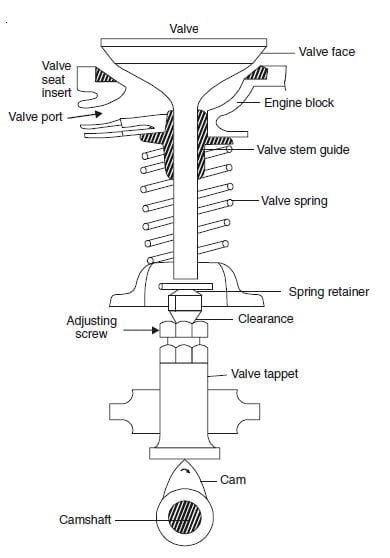
There are two main layouts:
- Push rod and rocker (OHV): the camshaft sits low in the block. A cam lifts a tappet, which pushes a long push rod up to a rocker arm on the head; the rocker pivots and presses the valve open. Simple and compact in height, but the many parts limit high-speed operation. Still seen in some tractor and stationary diesel engines.
- Overhead camshaft (OHC): the camshaft is on the cylinder head and works the valves directly through bucket tappets or short rocker fingers. Fewer moving parts means stable valve timing at high rpm. Single overhead cam (SOHC) uses one shaft; double overhead cam (DOHC) uses one for inlet and one for exhaust valves, which allows four valves per cylinder. Most current car engines are DOHC.
Timing belt or chain: the camshaft is driven from the crankshaft by a toothed rubber belt, a roller chain or gears, always at a 2:1 ratio. A belt is quieter but must be replaced at the interval the maker specifies; a chain usually lasts the life of the engine but is heavier. Gears are used in many heavy diesels.
Engine systems in brief
- Fuel system: older petrol engines used a carburettor to mix fuel with air. Modern petrol engines use electronic fuel injection, into the inlet port or directly into the cylinder. Diesel engines use a high-pressure pump and injectors; most new diesels use a common-rail system.
- Ignition: a petrol (SI) engine uses an ignition coil and spark plug to fire the compressed mixture. A diesel (CI) engine has no spark plug; the fuel injector sprays fuel into air that compression has made hot enough to ignite it. Diesels may have glow plugs to help cold starting.
- Cooling system: water pump, radiator, thermostat and fan (or fins and airflow on air-cooled two-wheeler engines) keep metal temperatures within limits.
- Lubrication system: oil pump, strainer, filter and oil galleries feed oil under pressure to the bearings, cam and cylinder walls.
- Starting system: a battery and starter motor crank the engine until it fires. See our pages on the starting system and the lead acid battery; older vehicles recharged the battery with a dynamo.
SI vs CI engine: how the components differ
| Item | SI (petrol) engine | CI (diesel) engine |
|---|---|---|
| Ignition | Spark plug and ignition coil | No spark plug; fuel injector, glow plug for cold start |
| Fuel supply | Port or direct injection at moderate pressure (carburettor in older engines) | High-pressure pump and injectors, usually common rail |
| Compression ratio | About 8 to 12 | About 14 to 22 |
| Block, head, crankshaft, connecting rod | Lighter | Heavier and stronger to take higher peak pressure |
| Load control | Throttle valve in the inlet | Quantity of fuel injected; no throttle needed |
| Starter and battery | Smaller | Larger, because the engine must be cranked faster against higher compression |
Worked examples on engine dimensions
1. Swept volume and engine displacement
Data: 4 cylinders, bore D = 73 mm, stroke L = 80 mm.
- Swept volume of one cylinder Vs = (π/4) D2 L. Work in cm: (π/4) x 7.32 x 8.0 = 0.7854 x 53.29 x 8.0 = 334.8 cm3.
- Total displacement = 4 x 334.8 = 1339 cm3, which would be sold as a 1.3 litre engine.
2. Compression ratio from swept and clearance volume
Compression ratio r = (Vs + Vc) / Vc, where Vc is the clearance volume left above the piston at top dead centre. If the same engine has Vc = 37.2 cm3:
r = (334.8 + 37.2) / 37.2 = 372.0 / 37.2 = 10.0. That is a typical petrol figure. Working backwards, Vc = Vs / (r – 1) = 334.8 / 9 = 37.2 cm3, which confirms it. A diesel with r = 18 would need Vc of only Vs/17, so the clearance space is much smaller.
3. Mean piston speed
The piston travels 2L per revolution, so mean piston speed vp = 2LN/60, with L in metres and N in rpm. For the same engine at 6000 rpm:
vp = 2 x 0.080 x 6000 / 60 = 16 m/s. Mean piston speed limits how fast an engine can safely run, because inertia forces on the piston, rings and connecting rod grow with it.
Common mistakes students make
- Writing that the camshaft turns at crankshaft speed. In a four-stroke engine it turns at half speed.
- Listing a spark plug among diesel engine components. A CI engine ignites by compression; a glow plug only helps a cold start.
- Forgetting the clearance volume in the compression ratio. r is not Vs/Vc; it is (Vs + Vc)/Vc.
- Using bore in mm and stroke in cm in the same formula. Convert both to cm first to get cm3 (cc).
For the full sequence of strokes these parts perform, see the four-stroke engine article on Wikipedia.
FAQs
What are the main components of an IC engine?
Cylinder block, cylinder head, crankcase, piston and piston rings, gudgeon pin, connecting rod, crankshaft, flywheel, camshaft, valves, and a spark plug (petrol) or fuel injector (diesel).
Which part converts reciprocating motion into rotary motion?
The connecting rod and crankshaft together. The rod carries the piston’s push to the offset crankpin, and the crankshaft turns it into rotation.
What is the difference between a wet liner and a dry liner?
A wet liner is in direct contact with the coolant and needs sealing rings; a dry liner is pressed into the block bore and never touches the coolant.
Why does a piston have more than one ring?
The upper compression rings seal combustion gas and pass heat to the cylinder wall, while the bottom oil control ring scrapes surplus oil off the wall so it does not burn.
What is the function of the flywheel in an IC engine?
It stores energy during the power stroke and releases it during the other strokes, which keeps crankshaft speed steady. It also carries the starter ring gear and the clutch face.