 EngineeringHulk
- Home
- Blog
- Automobile Engineering
- Bendix Drive in a Starter Motor: Working, Construction and Modern Alternatives
Bendix Drive in a Starter Motor: Working, Construction and Modern Alternatives
On this page
- Why a starter needs a drive mechanism at all
- Construction of an inertia-type Bendix drive
- Working of the Bendix drive
- Failure modes of the inertia drive
- The pre-engaged starter: what modern cars use
- Inertia vs pre-engaged starter drive
- Gear-reduction and permanent-magnet starters
- References
- FAQs
- Related Topics on EngineeringHulk
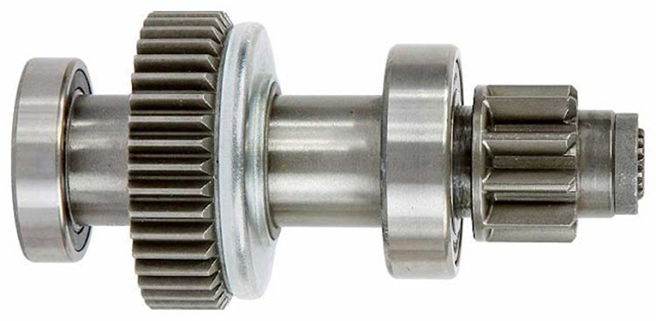
A Bendix drive is the mechanism that pushes a starter motor’s pinion into mesh with the engine’s flywheel ring gear to crank the engine, then pulls it straight back out the moment the engine fires. The classic inertia type does this with no electrical help at all: the pinion is carried on a coarse screw thread, and its own inertia makes it lag behind the spinning armature shaft so that it screws itself forward into mesh. When the engine starts and the ring gear begins driving the pinion faster than the shaft, the thread reverses the action and throws the pinion out.
The inertia Bendix drive is a historical design. It was invented by Vincent Bendix around 1914 and it dominated starter motors for roughly sixty years, but no modern car uses it. Today’s cars use the pre-engaged starter with a solenoid, shift lever and overrunning clutch. Both are in the syllabus, and the comparison between them is the part examiners actually ask about.
Why a starter needs a drive mechanism at all
A starter motor has one hard problem. It must be coupled to the engine to crank it, and it must be uncoupled from the engine a fraction of a second later, and nobody is going to do that by hand.
The reason for the urgency is the gear ratio. A flywheel ring gear typically has 120 to 160 teeth and a starter pinion has 9 to 12, so the reduction between starter and engine is roughly 10:1 to 16:1. That ratio is what lets a small motor turn a cold engine: the motor supplies modest torque at high speed, and the gearing trades that speed for the several hundred newton metres needed to turn the crankshaft against compression.
Run the arithmetic the other way and the danger is obvious. Take a 12:1 ratio.
- Cranking at 200 rpm gives an armature speed of 200 × 12 = 2400 rpm. Perfectly normal.
- The engine fires and picks up to 1500 rpm, still engaged: 1500 × 12 = 18 000 rpm.
- The driver blips it to 3000 rpm: 3000 × 12 = 36 000 rpm.
A starter armature is a heavy laminated core carrying copper windings held in place by band or wedge, running in plain bushes. It is built for a few thousand rpm for a few seconds at a time. At 18 000 rpm the centrifugal loading on the windings is many times what the design allows; the commutator can throw its segments, the windings can be flung out of their slots, and the armature can burst. That is the real failure being designed against, and it happens in well under a second after the engine catches.
So the drive mechanism has to do three things: engage on cranking, transmit high torque while engaged, and disengage instantly once the engine runs faster than the starter.
Construction of an inertia-type Bendix drive
| Part | What it is | What it does |
|---|---|---|
| Threaded sleeve (screwed sleeve) | A sleeve carrying a coarse-pitch, quick-start external thread, splined or keyed to the armature shaft | Turns with the armature and provides the screw along which the pinion travels into and out of mesh |
| Pinion with counterweight | A small gear, usually 9 to 12 teeth, internally threaded to match the sleeve, cast with a deliberately heavy and unbalanced section on one side | The extra mass raises its inertia so that it resists turning with the shaft. That resistance is what makes it screw itself along the thread instead of just spinning |
| Drive spring (Bendix spring) | A heavy coil spring connecting the threaded sleeve to the drive head on the armature shaft | Absorbs the shock of engagement and acts as the torsional link that carries cranking torque. It is a spring in series with the drive, not a return spring |
| Drive head / collar | The fixed member keyed to the armature shaft, to which one end of the drive spring is bolted | Transmits armature torque into the spring |
| Anti-drift spring | A light spring or friction washer acting on the pinion | Stops the pinion creeping into mesh on its own from road vibration when the engine is running and the starter is idle |
| Pinion stop / stop nut | A collar at the end of the thread | Limits pinion travel so it stops at full mesh depth in the ring gear and cannot run off the sleeve |
| Flywheel ring gear | A hardened steel ring, usually shrunk onto the flywheel rim, with chamfered tooth ends | The gear the pinion meshes with. The chamfer helps the teeth find each other on engagement |
The pinion teeth on a Bendix drive have a chamfered leading edge for the same reason, and the assembly runs dry. Oil or grease on the sleeve thread is a fault, not maintenance, because it collects road dust and gums the thread solid.
Working of the Bendix drive
Engagement
Turn the key and full battery current goes to the starter motor, so the armature shaft and the threaded sleeve accelerate hard from rest. The pinion is screwed onto that sleeve and has substantial mass in its unbalanced counterweight, so its own inertia makes it lag behind. Relative to the sleeve it is effectively turning backwards, and because it is threaded onto the sleeve, that relative rotation drives it along the thread. In perhaps a tenth of a second the pinion travels forward and meshes with the flywheel ring gear, running up against the pinion stop at full mesh.
Cranking
With the pinion stopped hard against the collar, it can no longer screw forward, so it must now turn with the shaft. Armature torque passes through the drive head, into the drive spring, along the sleeve and out through the pinion into the ring gear, and the engine turns over.
The drive spring is the part that saves the mechanism here. The armature is already spinning at a few thousand rpm when the pinion suddenly grabs a dead engine that is not moving at all. Without the spring, that collision would go straight into the teeth and the shaft as an impact load. The spring winds up instead, spreading the torque rise over several milliseconds and cushioning the shock. It also lets the pinion slip a little if the engine kicks back during compression, which is common on a cold start and used to break the wrists of drivers using a starting handle.
Disengagement
The engine fires. Within a moment the ring gear is driving the pinion faster than the armature shaft is turning it. The relative motion between pinion and sleeve now reverses, and the same thread that pulled the pinion into mesh screws it straight back out. The anti-drift spring holds it there, out of mesh, until the next start.
This is the elegance of the design: no solenoid, no lever, no electrical signal to disengage, just a thread that reads which side is driving. It is also the design’s weakness, because engagement and disengagement are both violent and neither is controlled.
Variants: folo-thru and barrel type
- Folo-thru drive. A refinement with a detent pin and a small latch that locks the pinion in the engaged position once it is fully home. It cannot bounce back out during a slow or stuttering start, which the plain inertia drive is prone to. The latch is released by centrifugal force only when pinion speed rises past a set value, meaning the engine has genuinely started. Common on aircraft piston engines and heavier equipment.
- Barrel type (outboard drive). The spring and sleeve are enclosed within a barrel or housing rather than being exposed. It keeps dirt off the thread and contains the parts if the spring breaks, and it was used where the starter was in a dirty position.
Failure modes of the inertia drive
| Fault | Symptom | Cause |
|---|---|---|
| Broken drive spring | Starter spins fast and freely, engine does not turn at all | Fatigue from repeated shock loading, or one severe engine kickback. With the spring broken there is no torsional path from armature to pinion |
| Dirt-jammed thread | Starter whirs without engaging, or the pinion stays engaged after starting | Road grit and old grease gum the coarse thread so the pinion cannot slide. The single most common inertia-drive complaint, and often cleanable |
| Worn or chipped pinion teeth | Loud grinding or clattering on engagement, intermittent cranking | Repeated clash with the ring gear. Tooth ends round over and lose the chamfer that guides engagement, which makes the clashing worse |
| Ring gear tooth damage | Grinding at one particular spot, or the starter spins with no cranking when the engine stops in certain positions | The pinion smashing into a stationary ring gear. Damage clusters at the positions where the engine most often stops, which is why the fault appears intermittent |
| Pinion held in mesh after starting | Screaming noise from the starter with the engine running; starter destroyed in seconds | Jammed thread, weak or broken anti-drift spring, worn sleeve. This is the overspeed case described above |
| Pinion drifting into mesh while driving | Intermittent scraping or whining at speed | Failed anti-drift spring letting vibration walk the pinion forward |
The pattern behind almost all of these is the same. The inertia drive engages by throwing a spinning gear at a stationary one and hoping the teeth line up. When they do not, something has to give.
The pre-engaged starter: what modern cars use
The pre-engaged starter fixes the inertia drive’s two weaknesses. It meshes the gears before the motor develops full torque, and it disengages through a one-way clutch instead of relying on a thread and luck.
Main parts
- Solenoid – an electromagnet with a movable plunger, mounted on top of the starter, containing two windings and a heavy-duty contact set.
- Shift lever (fork) – a pivoted lever linking the solenoid plunger to the drive assembly, so plunger movement slides the pinion along the shaft.
- Overrunning clutch (one-way roller clutch, freewheel) – the pinion’s coupling to the shaft. It drives in one direction and freewheels in the other.
- Helical splines on the armature shaft, which give the pinion a slight screwing motion to help the teeth find mesh.
- Return spring in the solenoid to pull everything back out when the key is released.
The two-stage solenoid action
This is the heart of the design and the part worth learning properly. The solenoid has two windings wound in the same direction on the same former.
- Key turned. A light current from the ignition switch energises both the pull-in winding (thick wire, few turns, low resistance, connected through the motor) and the hold-in winding (thin wire, many turns, earthed to the body). Together they create a strong magnetic pull and the plunger begins to move.
- Stage one – engagement. The plunger drags the shift lever, which slides the drive assembly along the shaft until the pinion meets the ring gear. Meanwhile the small current flowing through the pull-in winding passes on into the motor field and armature. It is enough to turn the armature slowly, an inch at a time, so if the teeth happen to be butted tooth-to-tooth, that slow creep rotates them until they drop into mesh. A meshing spring behind the pinion takes up the difference.
- Stage two – cranking. Only when the plunger reaches the end of its travel, with the pinion fully meshed, does it close the heavy main contacts. Now full battery current, which can be 200 to 400 A on a car and far more on a diesel, flows directly to the motor and the engine cranks.
- Pull-in winding switches off. Closing the main contacts puts the same battery voltage on both ends of the pull-in winding, so current through it falls to zero. The hold-in winding alone keeps the plunger there, drawing only a small current. This is why a starter with a failed hold-in winding chatters: the plunger pulls in, the contacts close, the pull-in winding cancels, there is nothing left to hold it, it springs back out, and the cycle repeats several times a second.
- Release. Let go of the key, the solenoid de-energises, the return spring opens the main contacts and pulls the pinion out of mesh.
Why the overrunning clutch is the better answer
Inside the drive is a roller clutch: an outer shell driven by the armature shaft’s helical splines, an inner hub carrying the pinion, and spring-loaded rollers sitting in wedge-shaped ramps between them.
- Starter drives engine. The rollers are pushed into the narrow part of their ramps, wedge solid and lock the two members together, so full cranking torque goes to the pinion.
- Engine drives starter. The relative motion reverses, the rollers roll back to the wide part of the ramps, and the clutch releases. The pinion is now free to spin at ring-gear speed while the armature carries on at its own pace.
The important consequence is that overspeed protection no longer depends on the pinion physically getting out of mesh. Even if the driver holds the key on for two seconds after the engine fires, the clutch simply freewheels and the armature is never dragged above its own speed. The inertia drive has no such margin: if its thread sticks, the armature goes to 18 000 rpm and is scrap. Being able to mesh the gears gently before applying torque also means the teeth stop being hammered, which is why ring gears on modern cars last the life of the engine.
Inertia vs pre-engaged starter drive
| Feature | Inertia (Bendix) drive | Pre-engaged drive |
|---|---|---|
| Engagement method | Pinion inertia screws it along a coarse thread once the armature spins | Solenoid plunger and shift lever push the pinion into mesh mechanically |
| Order of events | Motor spins first, pinion meshes afterwards, at speed | Pinion meshes first, then full current flows and the motor cranks |
| Disengagement method | Ring gear overruns the shaft and the thread unscrews the pinion | Overrunning roller clutch freewheels; solenoid withdraws the pinion when the key is released |
| Shock absorption | Heavy drive spring in series with the drive | Meshing spring plus the clutch; loads are far lower to begin with |
| Tooth clash | Frequent, and the usual cause of ring-gear wear | Rare; the slow pre-mesh rotation lets the teeth index into position |
| Overspeed protection | Depends on the thread working freely every single time | Guaranteed by the one-way clutch, independent of pinion position |
| Control circuit | A simple heavy-duty switch carrying full starter current | Ignition switch carries only solenoid current; the solenoid switches the heavy current close to the motor |
| Cable losses | Long heavy cable run to the dashboard switch, with voltage drop | Short, thick cable from battery to the solenoid on the starter itself |
| Noise on starting | Loud whirr and a characteristic clash | A single clunk, then cranking |
| Cost and complexity | Low; few parts | Higher; solenoid, lever, clutch |
| Repeat starting | Poor. Prone to bouncing out during a hesitant start | Good. Stays meshed for as long as the key is held |
| Current status | Historical. Older cars, some small engines, lawnmowers, generator sets | Current standard on every modern car, van, truck and motorcycle with an electric starter |
Gear-reduction and permanent-magnet starters
Two further developments sit on top of the pre-engaged design, and both are now normal fitment.
Gear-reduction starters put an additional reduction, usually around 3:1 to 4.5:1 and often an epicyclic (planetary) set, between the armature and the drive. The armature can then be small and spin fast, which is where an electric motor is efficient, while the pinion still turns slowly with high torque. The result is a starter that is smaller and lighter than an equivalent direct-drive unit, draws less current, and cranks better on a weak battery or a cold morning. The drive end still uses a solenoid, shift lever and overrunning clutch exactly as described above.
Permanent-magnet starters replace the wound field coils and their pole shoes with rare-earth or ferrite magnets. Removing the field windings saves weight and copper and removes the field current draw. Most are combined with a gear reduction, giving the compact PMGR (permanent-magnet gear-reduction) starter found on the majority of petrol cars sold today.
Integrated starter-generators take the next step and remove the pinion entirely. A belt-driven or crank-mounted electric machine both starts the engine and generates, which is what makes stop-start systems practical. A stop-start car may restart its engine dozens of times in a single commute, a duty cycle that would destroy a conventional pinion-and-ring-gear starter in months. For the wider circuit and battery context, see the starting system in automobile engineering.
References
- NPTEL – Online Engineering Courses, automotive electrical and electronics lecture series.
FAQs
What is a Bendix drive and how does it work?
A Bendix drive is the self-engaging mechanism in an inertia-type starter motor. The pinion sits on a coarse thread on the armature shaft and carries a heavy unbalanced weight. When the armature spins up, the pinion’s inertia makes it lag and screw itself into mesh with the flywheel ring gear. Once the engine fires and drives the pinion faster than the shaft, the thread screws it back out.
What does the Bendix drive spring do?
It is the torsional link between the armature shaft and the pinion, and it absorbs the shock when a spinning starter suddenly picks up a stationary engine. Without it, engagement would be a direct impact on the gear teeth and the shaft. It also lets the pinion give a little if the engine kicks back during compression. A broken drive spring makes the starter spin freely without turning the engine.
Why do modern cars not use inertia-type Bendix drives?
Because the inertia drive engages by throwing a spinning pinion at a stationary ring gear, which clashes the teeth, and because its overspeed protection depends on the thread sliding freely every time. If the thread sticks, the engine drives the armature to 18 000 rpm or more and wrecks it. Pre-engaged starters mesh the gears before full current flows and disengage through a one-way clutch that cannot stick in the driving direction.
What is the gear ratio between the starter pinion and the flywheel?
Roughly 10:1 to 16:1 on a car. A flywheel ring gear usually carries 120 to 160 teeth against a pinion of 9 to 12 teeth. The reduction trades the motor’s speed for the torque needed to turn a cold engine against compression, and it is also the factor by which engine speed would be multiplied at the armature if the pinion stayed engaged.
What is the difference between an inertia drive and a pre-engaged starter?
An inertia drive uses the pinion’s own mass and a screw thread to engage and disengage, with no electrical control. A pre-engaged starter uses a solenoid and shift lever to mesh the pinion first, closes the main contacts only after full mesh, and uses an overrunning roller clutch to release drive when the engine takes over. The inertia type is historical; the pre-engaged type is what every modern vehicle uses.
Related Topics on EngineeringHulk
Keep reading
Lead Acid Battery in Automobiles: Construction, Working and Types
Lead acid battery construction explained part by part: plates, grids, separators, electrolyte, cell chemistry, SMF/AGM/EFB types, ratings and a worked example.

Dynamo in Automobile Engineering: Construction, Working, Control Box and Dynamo vs Alternator
Automobile dynamo meaning, construction for a diagram, working, cut-out and regulator, a worked EMF example, and a clear dynamo vs alternator comparison.

Propeller Shaft and Universal Joints: Construction, Working and Types
How a propeller shaft carries drive through changing angle, length and torque, why the tube is hollow, and how Hooke joints differ from CV joints.

Synchromesh Gear Box: Construction, Working, Types and Common Faults
How a synchromesh gear box works: synchroniser hub, sleeve, baulk ring and cone, the blocking action, cone types, power flow and common gearbox faults.

Constant Mesh Gearbox: Construction, Working, Diagram and Gear Ratios
Constant mesh gearbox construction and working: gears always in mesh, dog clutches lock them to the main shaft. Diagram, power path, gear ratio example.
Sliding Mesh Gear Box: Construction, Working and Power Flow
A sliding mesh gear box selects a ratio by sliding spur gears along a splined mainshaft into mesh. Layout, power path, double declutching and limits.