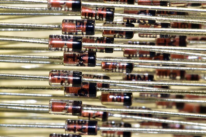
The most common application of a Zener diode is as a voltage regulator: connected in reverse bias with a series resistor, it holds the voltage across a load close to its Zener voltage (for example 5.1 V) even when the supply or load current changes. Zener diodes are also used as voltage references, clippers and limiters, over-voltage and surge protectors, meter protectors, waveform shapers and level shifters.
A Zener diode is a silicon PN junction built to work safely in reverse breakdown. Once the reverse voltage reaches the Zener voltage VZ, the diode conducts and the voltage across it stays almost constant over a wide range of current.

Zener breakdown vs avalanche breakdown
Two different mechanisms produce the breakdown, and which one dominates depends on the voltage rating:
- Zener effect (below about 5 V): the junction is very heavily doped and very thin, so the electric field is strong enough for electrons to tunnel straight across. This gives a negative temperature coefficient: VZ falls slightly as the diode warms.
- Avalanche effect (above about 6 V): in a lightly doped, wider junction, carriers gain enough energy to knock out more carriers, which multiply. This gives a positive temperature coefficient.
Between roughly 5 and 6 V both mechanisms act together and the temperature coefficients nearly cancel. The Diodes Inc. datasheet for the 1N47xxA series shows this crossover: the 3.3 V 1N4728A drifts by -0.08 to -0.05 %/°C, the 5.1 V 1N4733A by -0.01 to +0.04 %/°C, and the 15 V 1N4744A by +0.055 to +0.09 %/°C. That is why diodes near 5.1 to 5.6 V are the most temperature-stable. All of them are still called “Zener diodes” by convention.
Uses of Zener diodes: the main applications
1. Shunt voltage regulator
This is the textbook answer to “a typical application for Zener diodes is as a…” The circuit is a series resistor RS from the unregulated supply, and the Zener connected across the load with its cathode to the positive side. By Kirchhoff’s current law, the resistor current splits into the Zener current and the load current: IR = IZ + IL. When the load draws less, the Zener takes more, and vice versa, so the output stays near VZ. The Zener is called a shunt regulator because it sits in parallel with the load.
Worked design: 5.1 V regulator
Given: supply varies from 9 V to 12 V; load current varies from 0 to 30 mA; Zener is a 1N4733A (VZ = 5.1 V, 1 W, IZK = 1 mA).
Step 1: choose a minimum Zener current. The Zener must stay above its knee current in the worst case. IZK is 1 mA; take IZ(min) = 5 mA for margin.
Step 2: find the largest allowed RS. The worst case for keeping regulation is the lowest supply with the highest load current:
RS(max) = (Vin(min) – VZ) / (IL(max) + IZ(min)) = (9 – 5.1) / (0.030 + 0.005) = 3.9 / 0.035 = 111 Ω
Choose the next lower standard value, 100 Ω.
Step 3: check the low-supply case with 100 Ω. IR = 3.9 / 100 = 39 mA. With 30 mA to the load, IZ = 9 mA, comfortably above the knee.
Step 4: check Zener power in the worst case. The Zener works hardest at the highest supply with no load, because it must absorb all the resistor current:
IR = (12 – 5.1) / 100 = 6.9 / 100 = 69 mA, so PZ = 5.1 × 0.069 = 0.35 W.
That is 35 percent of the 1 W rating, a sensible margin since the rating is derated above 50 °C lead temperature. A 0.5 W Zener would be too tight.
Step 5: resistor power. PR = 6.92 / 100 = 0.48 W, so use a 1 W resistor.
Step 6: efficiency. At 12 V in and a 30 mA load, output power = 5.1 × 0.030 = 0.153 W and input power = 12 × 0.069 = 0.83 W. Efficiency is only about 18 percent, which is the main weakness of this circuit.
Also note that the output is not perfectly fixed. The Zener current here swings from 9 mA to 69 mA, and the datasheet dynamic impedance of about 7 Ω (at the 49 mA test current) means the output moves by roughly 60 mA × 7 Ω ≈ 0.4 V across that range. Add the 5 percent tolerance on VZ (about 4.85 V to 5.36 V) and you see why a Zener shunt regulator suits light, non-critical loads.
2. Voltage reference
A Zener fed from a steady current gives a known voltage for comparators, ADC inputs, power-supply feedback loops and bias circuits. Feeding it from a constant-current source instead of a resistor removes most of the variation from supply changes. For best temperature stability, pick a rating near 5.1 to 5.6 V, or use a temperature-compensated reference diode.
3. Clipper and limiter
A Zener placed across a signal line clips any excursion above VZ in one direction and at about 0.7 V (its forward drop) in the other. Two Zeners connected back to back (anode to anode) clip both halves symmetrically at about VZ + 0.7 V. With a series resistor in front, this is a simple way to limit the input to an amplifier or microcontroller pin.
4. Over-voltage and transient protection
A Zener across a supply rail stays off in normal operation and clamps the voltage if it rises above VZ. For heavier faults the Zener is used to trigger a crowbar circuit: the Zener drives the gate of an SCR across the rail. If the supply overshoots, the Zener conducts, the SCR fires and short-circuits the rail, and the resulting current blows a fuse or trips the supply’s current limit, so the load never sees the over-voltage. See how the SCR latches in our page on the thyristor (SCR).
For fast, high-energy spikes (lightning-induced surges, inductive kick-back, ESD) a TVS diode is the better part. It is a breakdown diode built with a large junction to absorb short pulses: the SMBJ family is rated for 600 W and the 1.5KE family for 1500 W peak pulse power on a 10/1000 µs surge. An ordinary 1 W Zener is meant for steady regulation and can fail under that kind of pulse.
5. Meter protection
A Zener connected across a moving-coil meter (with the meter’s series resistor) bypasses current when the voltage exceeds a safe level, so an accidental over-range does not bend the pointer or burn the coil.
6. Waveform shaping
Feeding a sine wave through a resistor into back-to-back Zeners gives a nearly square wave of fixed amplitude. This is a simple way to make a clean square signal or a fixed-amplitude clock from a sine source.
7. Level shifting
A Zener placed in series with a signal subtracts roughly VZ from it. This shifts a signal down to suit another stage, for example to turn on a transistor only when the input exceeds a threshold, or to drop a supply by a fixed amount.
Zener diode key ratings (1N47xxA series example)
The values below are from the Diodes Inc. datasheet for the 1 W, DO-41 1N4728A to 1N4761A family, at 25 °C. Standard tolerance on VZ is 5 percent. The maximum Zener current is given as IZ = Pd / VZ.
| Rating | What it means | 1N4733A | 1N4740A |
|---|---|---|---|
| VZ | Nominal Zener voltage at the test current | 5.1 V | 10 V |
| Tolerance | Allowed spread of VZ | ±5 % | ±5 % |
| Pd | Maximum power dissipation (derate 6.67 mW/°C above 50 °C) | 1 W | 1 W |
| IZT | Test current at which VZ is specified | 49 mA | 25 mA |
| ZZT | Maximum dynamic impedance at IZT | 7 Ω | 7 Ω |
| IZK | Knee current: stay above this to regulate | 1 mA | 0.25 mA |
| ZZK | Maximum impedance at the knee | 550 Ω | 700 Ω |
| IZ(max) = Pd/VZ | Continuous current limit | about 196 mA | 100 mA |
Note how much higher the impedance is at the knee (550 Ω) than at the test current (7 Ω). Running a Zener close to IZK saves power but makes the voltage much less stable.
Advantages of Zener diodes
- Very cheap and small, with standard ratings from about 2.4 V to well over 100 V.
- Simple: a regulator or reference needs only one diode and one resistor.
- Responds quickly to changes in load or supply.
- Works as a clamp in both directions: breakdown one way, normal forward conduction the other.
- Near-zero temperature drift around 5 to 6 V ratings.
Disadvantages of Zener diodes
- Poor efficiency. The series resistor and the Zener waste power all the time, as the worked example shows (about 18 percent).
- Limited current. Practical only for loads of tens of milliamps; larger loads need an impractically large Zener or a series pass transistor.
- VZ drift. Voltage changes with current (dynamic impedance), with temperature away from 5 to 6 V, and has a 5 percent tolerance on standard parts.
- Noise. Avalanche breakdown generates noticeable electrical noise, especially at low current; this is bad for precision analog circuits (and is exploited on purpose in noise generators).
- Poor regulation at low current near the knee.
When to use an LDO or a TL431 instead
| Need | Better choice | Why |
|---|---|---|
| A regulated supply for a real load (tens to hundreds of mA) | Linear regulator or LDO | Draws only what the load needs plus a small quiescent current, and regulates far more tightly |
| High efficiency or large current | Switching (buck) regulator | Efficiency well above any linear circuit |
| A precise or adjustable reference | TL431 shunt reference | Internal 2.495 V reference, set from 2.495 V up to 36 V with two resistors, sinks 1 to 100 mA, available in 0.5, 1 and 2 percent grades |
| Surge and ESD protection | TVS diode | Rated for large pulse energy |
| Cheap clamp, simple bias, a few mA | Zener | Still the simplest part for the job |
The PN junction physics behind breakdown is covered in the NCERT Class 12 Physics chapter on semiconductor electronics; for more on the junction itself see this overview of the PN junction.
FAQs
What are Zener diodes used for?
Mainly as simple voltage regulators and voltage references. They are also used for clipping and limiting signals, over-voltage protection (often triggering an SCR crowbar), meter protection, waveform shaping and level shifting.
Why is a Zener diode connected in reverse bias?
Its useful property, a nearly constant voltage over a wide current range, appears only in reverse breakdown. In forward bias it behaves like an ordinary silicon diode with a drop of about 0.7 V.
Why is a series resistor needed with a Zener diode?
The resistor limits the current. Without it, once the supply exceeds VZ the current would rise until the diode overheated. The resistor also drops the difference between the supply and VZ.
What is the difference between Zener and avalanche breakdown?
Zener breakdown is tunnelling across a thin, heavily doped junction and dominates below about 5 V, with a negative temperature coefficient. Avalanche breakdown is carrier multiplication in a wider junction, dominates above about 6 V and has a positive temperature coefficient.
Can a Zener diode regulate a high-current load?
Not on its own. It is practical only for a few tens of milliamps. For larger loads, use the Zener to set the base voltage of a series pass transistor, or use a linear or switching regulator IC.