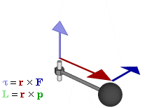
The moment of a force is the turning effect that force produces about a point or an axis, and it equals the force multiplied by the perpendicular distance from that point to the line of action of the force: M = F × d. The SI unit is the newton-metre (N·m). A 150 N pull on a spanner held 300 mm from the bolt centre gives a moment of 150 × 0.3 = 45 N·m, and the same pull applied 150 mm from the centre gives only 22.5 N·m, which is the whole reason long spanners exist.
What is the moment of a force?
A force does two things to a body. It pushes the body along its line of action, and unless that line passes through the point you are measuring about, it also twists the body around that point. The second effect is the moment.
Three things fix the moment of a force about a point O:
- The magnitude of the force, F. Double the force and you double the moment.
- The perpendicular distance, d, from O to the line of action of the force. This is called the moment arm or lever arm. It is not the distance to the point where the force is applied unless the force happens to be perpendicular to that line.
- The sense of rotation, clockwise or anticlockwise, which is what makes a moment a vector quantity rather than a plain number.
Moment is a vector. In full vector form, M = r × F, where r is the position vector from O to any point on the line of action. The magnitude works out as M = F r sin θ, where θ is the angle between r and F, and r sin θ is exactly the perpendicular distance d. The direction of M is along the axis of rotation, given by the right-hand rule.
Moment of a force formula, units and a worked example
M = F × d, with F in newtons and d in metres, gives M in newton-metres.
| Unit | Equal to | Where you meet it |
|---|---|---|
| N·m | SI unit | Torque wrench settings, machine design, physics problems |
| N·mm | 0.001 N·m | Small fasteners, instrument work, stress calculations in mm units |
| kN·m | 1000 N·m | Bending moments in beams, foundation design, structural drawings |
| kgf·m | 9.81 N·m | Older Indian workshop data and service manuals |
| lbf·ft | 1.356 N·m | Imported automotive and oilfield torque specifications |
Worked example: tightening a bolt with a spanner
A spanner is 300 mm long, measured from the bolt centre to the point where you grip it. You pull with 150 N.
- Pull at right angles to the handle. The perpendicular distance is the full 0.3 m, so M = 150 × 0.3 = 45 N·m.
- Pull at 60° to the handle. Now d = 0.3 sin 60° = 0.2598 m, so M = 150 × 0.2598 = 39.0 N·m. You lost 13% of the turning effect by pulling at an angle, even though your hand effort did not change.
- Pull along the handle, straight at the bolt. The line of action passes through the bolt centre, d = 0, so M = 0. The bolt does not turn at all, however hard you pull.
- Design question: your maximum comfortable pull is 120 N and the bolt needs 45 N·m. Required arm = 45 / 120 = 0.375 m, so you need a 375 mm spanner or an extension bar.
Student tip: when a workshop manual says “torque the head bolts to 45 N·m”, that number is a moment, and it assumes you are pulling at right angles to the wrench. Reading the same setting off a torque wrench used at an angle, or with an offset adaptor on the end, gives the bolt a different clamp load than the manual intended.
Why the perpendicular distance, and not just the distance
Split the force into two components: one along the line joining the pivot to the point of application, and one at right angles to it. The component pointing straight at the pivot has no moment arm, so it contributes nothing to the turning effect. It only tries to pull or push the body bodily towards or away from the pivot. Only the perpendicular component turns anything.
Writing M = F d sin θ, where d is the straight-line distance to the application point and θ is the angle between that line and the force, does the same job. Both forms collapse to zero when the force points at the pivot, which is the physical check to make when an answer looks odd.
This also explains a door. Push on the handle, far from the hinge, and the door swings easily. Push the same way close to the hinge and it barely moves. Push straight at the hinge line and nothing happens at all.
Sign convention for clockwise and anticlockwise moments
Moments about the same point add algebraically, so each one needs a sign. The convention used in Indian engineering mechanics courses and in most textbooks is:
- Anticlockwise moment: positive (+)
- Clockwise moment: negative (−)
This matches the right-hand rule with the z-axis out of the page, which is why it is the default in vector work. Some structural texts flip it and take clockwise as positive. Either is fine; what is not fine is changing convention halfway through a problem. Pick one, write it at the top of your answer sheet, and keep it for the whole question.
A practical habit: after finding an unknown reaction, check the sign physically. A negative answer for a support reaction means the support is pulling down rather than pushing up, which is real and happens at the end of an overhanging beam. A negative answer for a length or a distance means you made an arithmetic mistake.
Varignon’s theorem: the moment of a resultant equals the sum of the moments of its components
Varignon’s theorem states that the moment of a force about any point is equal to the algebraic sum of the moments of the components of that force about the same point. Because the components add up to the original force, the theorem works in both directions: you can replace a force by its components, or replace a set of concurrent forces by their resultant, without changing the moment about any point.
This is the single most useful result in statics, because measuring a perpendicular distance to a slanted line of action is fiddly, while the horizontal and vertical distances to the point of application are usually written straight on the diagram.
Worked example: checking Varignon’s theorem with numbers
A 500 N force acts at point A, which lies 2.0 m to the right of O and 1.5 m above it. The force is directed at 30° above the horizontal, pointing to the right and upwards. Take anticlockwise as positive.
Method 1, by components.
- Horizontal component: Fx = 500 cos 30° = 433.01 N, acting to the right at a height of 1.5 m above O. A rightward force above the pivot turns the body clockwise, so its moment is −1.5 × 433.01 = −649.52 N·m.
- Vertical component: Fy = 500 sin 30° = 250 N, acting upward at 2.0 m to the right of O. An upward force to the right of the pivot turns the body anticlockwise, so its moment is +2.0 × 250 = +500.00 N·m.
- Sum: −649.52 + 500.00 = −149.52 N·m, that is 149.5 N·m clockwise.
Method 2, by perpendicular distance. The line of action passes through (2.0, 1.5) with direction (cos 30°, sin 30°) = (0.8660, 0.5). The perpendicular distance from O is d = |2.0 × 0.5 − 1.5 × 0.8660| = |1.000 − 1.299| = 0.299 m. So M = 500 × 0.299 = 149.5 N·m, clockwise because the line of action passes above and to the left of O.
The two methods agree, which is Varignon’s theorem in one line. Method 1 needed no geometry beyond reading two coordinates off the sketch.
Resolving a force into components is itself the reverse of adding forces. If you need the rules for combining two forces into one, that is the parallelogram law of forces, which covers composition and resolution of concurrent forces; this page stays with the turning effects those forces produce.
Types of moments
| Type | What it is | Typical unit |
|---|---|---|
| Clockwise moment | Turns the body in the direction of clock hands about the chosen point. | N·m |
| Anticlockwise moment | Turns the body the opposite way. Opposite in sign to a clockwise moment. | N·m |
| Moment of a force about a point | F × perpendicular distance. Changes if you move the reference point. | N·m |
| Moment of a couple | Produced by two equal and opposite parallel forces. Has the same value about every point. | N·m |
| Bending moment | The internal moment at a section of a beam, found by summing the moments of all loads on one side of that section. | kN·m |
| Twisting moment or torque | A moment about the longitudinal axis of a shaft, which twists it. | N·m |
| First moment of area | Area × distance of its centroid from an axis, A·ȳ. Used to locate centroids and in shear-flow calculations. | mm³ |
| Second moment of area | Also called the area moment of inertia, I = ∫y²dA. Despite the name, it is not a turning effect at all. | mm⁴ |
The last two catch students out in exams. A first moment of area has units of mm³ and a second moment of area has mm⁴, so neither is a moment in newton-metres. If your units do not come out as force × length, whatever you have calculated is not the turning effect of a force.
What is a couple, and why its moment is the same about every point
A couple is a pair of equal, opposite, parallel forces whose lines of action are not the same line. The two forces cancel as far as straight-line motion is concerned, so a couple produces no resultant force at all. What it does produce is a pure turning effect, and the moment of a couple equals one force multiplied by the perpendicular distance between the two lines of action: M = F × a, where a is the arm of the couple.
Proof that the moment is independent of the point chosen
Take two vertical forces of magnitude F, one acting upward along a line, the other acting downward along a parallel line a metres away. Pick any point P on the line joining them, at a distance p from the upward force. Taking anticlockwise as positive:
- Moment of the upward force about P: the force is at distance p on one side, giving −F p.
- Moment of the downward force about P: it is at distance (a − p) on the other side, giving −F (a − p).
- Total: −F p − F a + F p = −F a.
The distance p cancels. The answer does not depend on where P was, so a couple has the same moment about every point in its plane and about every point out of it. That is the defining property of a couple, and it is why a couple can be shifted anywhere on a body, or turned in its own plane, without changing its effect. In vector language a couple moment is a free vector.
Properties of a couple
- The resultant force of a couple is zero, so a couple alone can never move a free body in a straight line; it only spins it.
- Its moment is the same about every point, so no reference point needs to be stated.
- Two couples in the same plane can be added algebraically, minding their signs.
- A couple can be replaced by any other couple of the same moment and sense: 40 N at 0.5 m and 100 N at 0.2 m are interchangeable, both being 20 N·m.
- A single force can be moved to a parallel line of action provided you add a couple to compensate. This “force-couple system” is how offset loads are handled in machine design.
Worked example: the couple on a steering wheel
A steering wheel is 380 mm in diameter. The driver pushes with 30 N at the top of the rim and pulls with 30 N at the bottom, both tangentially and in opposite directions. The arm of the couple is the full diameter, 0.38 m.
Moment of the couple = 30 × 0.38 = 11.4 N·m.
Check it about the wheel centre: each force is 0.19 m from the centre and both turn the wheel the same way, so the total is 30 × 0.19 + 30 × 0.19 = 11.4 N·m. Check it about the point where the upper hand grips: that force now has zero arm, and the lower force has an arm of 0.38 m, giving 30 × 0.38 = 11.4 N·m. Same answer from both points, as the proof above said it must be.
The practical consequence: because the two hand forces cancel, the steering column carries a pure 11.4 N·m twist and no sideways push. Steer with one hand instead, 60 N at 0.19 m, and you still get 11.4 N·m of turning effect but you also load the column and its bearings with a 60 N side force that the design did not ask for.
Moment of a force compared with moment of a couple
| Point of difference | Moment of a force | Moment of a couple |
|---|---|---|
| Produced by | One force | Two equal, opposite, parallel forces on different lines |
| Formula | M = F × perpendicular distance from the point to the line of action | M = F × perpendicular distance between the two forces |
| Resultant force | Equal to the force itself, so the body also tends to translate | Zero, so the body tends only to rotate |
| Depends on reference point | Yes, it changes if you take moments about a different point | No, it is the same about every point |
| Zero when | The line of action passes through the reference point | The two forces become collinear, so the arm is zero |
| Everyday example | Pulling a spanner, pushing a door open | Turning a steering wheel, a tap key, or a screwdriver held in both hands |
The principle of moments and equilibrium
The principle of moments states that when a body is in equilibrium under a coplanar force system, the algebraic sum of the moments of all the forces about any point is zero. Put the other way round: the sum of clockwise moments equals the sum of anticlockwise moments.
For a body to be in full equilibrium in a plane, three conditions must hold at once:
- ΣFx = 0, no net horizontal push
- ΣFy = 0, no net vertical push
- ΣM = 0 about any point, no net turning effect
The power of the third condition is that you get to choose the point. Take moments about a support and that support’s reaction disappears from the equation, because its line of action passes through the point you chose. One unknown drops out and a two-unknown problem becomes a one-line calculation.
Worked example: reactions of a simply supported beam
A beam AB spans 6 m on simple supports at A and B. It carries a 20 kN point load 2 m from A and a 30 kN point load 4.5 m from A. Self-weight is ignored. Find the support reactions RA and RB.
Step 1, take moments about A so that RA drops out. Clockwise moments from the downward loads must balance the anticlockwise moment of RB:
RB × 6 = (20 × 2) + (30 × 4.5) = 40 + 135 = 175 kN·m
RB = 175 / 6 = 29.17 kN
Step 2, vertical equilibrium. RA + RB = 20 + 30 = 50 kN, so RA = 50 − 29.17 = 20.83 kN.
Step 3, check by taking moments about B, which is the habit worth building. The load at 2 m from A is 4 m from B, and the load at 4.5 m from A is 1.5 m from B:
RA × 6 = (20 × 4) + (30 × 1.5) = 80 + 45 = 125, so RA = 125 / 6 = 20.83 kN, which agrees.
Notice that the larger reaction, 29.17 kN, is at B, the support nearer the heavier load. That is the physical sense check: if the arithmetic had put the bigger reaction at A, something would be wrong.
Worked example: a lever
A crowbar rests on a fulcrum. A 15 kg block sits 0.4 m from the fulcrum on one side, and you press down 1.2 m from the fulcrum on the other side. What effort is needed to just lift the block?
Weight of the block = 15 × 9.81 = 147.15 N. Its moment about the fulcrum = 147.15 × 0.4 = 58.86 N·m.
For balance, effort × 1.2 = 58.86, so effort = 49.05 N.
The mechanical advantage is 147.15 / 49.05 = 3, which is just the ratio of the two arms, 1.2 / 0.4. The lever multiplies force by trading distance for it, and the moment about the fulcrum is what makes the trade.
Moment vs torque vs bending moment
These three words are used loosely in conversation and precisely in exams, and readers conflate them constantly. All three have the units of force × length. The difference is which axis the turning is about and what it does to the material.
| Moment | Torque | Bending moment | |
|---|---|---|---|
| Meaning | The general turning effect of a force about a point or axis | A moment about the longitudinal axis of a shaft or fastener, which twists it | The internal moment carried at a section of a beam, which bends it |
| Axis | Any chosen point or axis | Along the length of the member | Across the member, perpendicular to its length |
| Effect on the member | Tends to rotate the body | Twisting, producing shear stress | Bending, producing tensile stress on one face and compressive on the other |
| Governing relation | M = F × d | T / J = τ / r = Gθ / L | M / I = σ / y = E / R |
| Usual unit | N·m | N·m | kN·m |
| Everyday case | Opening a door | A propeller shaft, a torque wrench on a bolt | A floor beam sagging between two walls |
In short: torque and bending moment are both moments; they are named after what they do to the member. Torque is a twisting moment about the member’s own axis, a bending moment bends the member across its axis, and “moment” on its own is the general term. A drive shaft under both effects at once is designed for the combination, not for either alone.
One more unit trap. Work and energy also come out as newton-metres, and 1 N·m of work is called 1 joule. A moment is never expressed in joules, because the two are physically different: work is force multiplied by distance moved along the line of action, while a moment is force multiplied by distance measured perpendicular to it. Keeping moments in N·m and energy in J avoids the confusion.
Applications of the moment of a force
- Hand tools. Spanners, wrenches and pipe wrenches all work by putting your hand force at the end of a long arm. A torque wrench measures and limits that moment so a fastener gets the right clamp load without being stretched past yield.
- Door and gate hardware. Handles are fitted on the far edge from the hinge for the largest possible arm. Door closers are sized by the moment they must overcome.
- Beams and structures. Support reactions, shear force and bending moment diagrams all start from taking moments. The bending moment diagram tells the designer where the beam needs the most depth or reinforcement.
- Cranes and excavators. The load moment about the tipping edge must stay below the stabilising moment from the counterweight and the machine’s own weight. Load moment indicators on site measure exactly that ratio.
- Vehicle steering and controls. Steering wheels, tap keys, screwdrivers and capstan wheels are all couples, applied so that the shaft gets twist without side load.
- Weighing and measurement. A steelyard balance, a beam balance and a spring-lever weighing machine all work on the principle of moments.
- Rotating machinery. The torque a motor delivers, the moment a gear tooth transmits, and the out-of-balance moment that causes vibration are all the same calculation applied to a spinning part.
Common mistakes when calculating moments
- Using the slant distance instead of the perpendicular distance. If the force is not at right angles to the line joining it to the pivot, you must either resolve the force or use d sin θ.
- Mixing units. Distances given in mm and forces in N give N·mm, not N·m. Convert before adding moments from different parts of a problem.
- Forgetting the sign. Moments are added algebraically. Two clockwise moments add; a clockwise and an anticlockwise one subtract.
- Stating a couple’s moment “about a point”. It does not need one, and writing “the moment of the couple about A” suggests you have not understood why it is the same everywhere.
- Taking moments about a badly chosen point. Choosing a point that no unknown passes through leaves you with two unknowns in one equation. Choose a support.
- Treating the second moment of area as a moment. Its unit is mm⁴. It describes the shape of a cross-section, not a turning effect.
References
- NCERT Physics – Systems of Particles and Rotational Motion, Class 11, Part 1.
- NPTEL – Engineering Mechanics lecture series, IIT.
- Torque – definition and vector formulation.
FAQs
What is the moment of a force?
The moment of a force is the turning effect it produces about a point or axis. It equals the magnitude of the force multiplied by the perpendicular distance from that point to the line of action of the force, M = F × d, and it is measured in newton-metres (N·m). It is a vector quantity, so every moment carries a sense, clockwise or anticlockwise.
What is the formula for the moment of a force and its unit?
M = F × d, where F is the force in newtons and d is the perpendicular distance in metres from the reference point to the line of action. The unit is the newton-metre, N·m. In full vector form M = r × F, whose magnitude is F r sin θ, where θ is the angle between the position vector r and the force. Useful conversions: 1 kgf·m = 9.81 N·m and 1 lbf·ft = 1.356 N·m.
Why is the moment of a couple the same about every point?
Because the two forces of a couple are equal and opposite, the distance from the reference point cancels out of the sum. Taking moments about a point p metres from one force gives −F p − F(a − p) = −F a, where a is the perpendicular distance between the forces. The answer depends only on F and a, never on where you took moments, so a couple has the same moment everywhere and produces no resultant force.
What is the difference between moment, torque and bending moment?
Moment is the general term for the turning effect of a force about a point or axis. Torque is a moment about the longitudinal axis of a shaft or bolt, which twists it and produces shear stress. A bending moment is the internal moment at a section of a beam, which bends it and produces tensile stress on one face and compressive stress on the other. All three have units of force multiplied by length, usually N·m or kN·m.
What is Varignon’s theorem?
Varignon’s theorem states that the moment of a force about any point equals the algebraic sum of the moments of its components about the same point. It lets you replace an awkward slanted force by its horizontal and vertical components and add their moments, which avoids measuring the perpendicular distance to a sloping line of action. It works in reverse too, so the moment of a resultant equals the sum of the moments of the forces it replaced.
Related Topics on EngineeringHulk
- 👉 Perpendicular Axis Theorem
- 👉 Shear Force & Bending Moment – Study Guide
- 👉 Strength of Materials – Study Guide
- 👉 Types of Metal: Detailed Classification
- 👉 Moment Distribution Method
- 👉 Shear Force & Bending Moment Diagrams – Structural Analysis (Civil)
- 👉 Degree of Static Indeterminacy
- 👉 Slope-Deflection Method
- 👉 Influence Lines