
TIG welding, or Gas Tungsten Arc Welding (GTAW), strikes an arc between a non-consumable tungsten electrode and the workpiece under a shield of inert gas, while filler metal is fed in separately by the welder’s other hand. Because the electrode is not melted into the joint, the welder controls heat and filler independently, which is why the TIG welding process gives the cleanest and most accurate welds of any manual arc process. It runs from about 0.5 mm sheet upwards, leaves no slag and no spatter, and is the standard choice for stainless steel, aluminium, titanium and root runs in pipe.
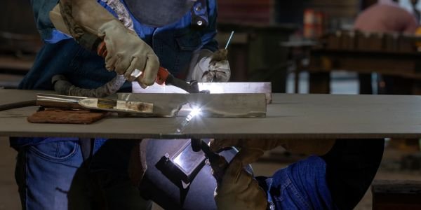
How the TIG welding process works
Three things happen at once inside a 2 mm gap between the tungsten tip and the plate.
- The arc. Current passes from the tungsten electrode to the work through ionised shielding gas. Arc column temperature sits in the 6,000 to 20,000 K band, far above the melting point of any structural metal.
- The shield. Argon flows out of the ceramic cup at roughly 6 to 12 litres per minute and pushes air off the pool. Without it the molten metal would take up oxygen and nitrogen in a second and the tungsten itself would burn back.
- The filler. The welder dips a bare filler rod into the leading edge of the pool, withdraws it, moves forward, and dips again. The rod tip never leaves the gas shield, or it oxidises and carries that oxide into the next dip.
The tungsten is called non-consumable because its melting point, 3,422 °C, is the highest of any metal. It erodes slowly and must be reground, but no part of it is meant to enter the weld. Anything of it that does end up in the bead is a defect called a tungsten inclusion.
Autogenous TIG is the version with no filler at all: the arc simply fuses the two edges together. Thin stainless sheet, tube-to-tube butt joints and orbital work in instrumentation tubing are usually done this way.
TIG welding equipment
| Item | What it does | What to look for |
|---|---|---|
| Power source | Supplies constant-current (drooping) output | A DC-only machine covers steel, stainless and copper. An AC/DC inverter with adjustable AC balance and frequency is needed for aluminium and magnesium. |
| Torch | Holds the electrode, carries current and gas | Air-cooled torches are rated to roughly 150 to 200 A at 60% duty cycle; water-cooled torches handle 300 A and above and stay slim in the hand. |
| Tungsten electrode | Sustains the arc | 1.0 to 4.0 mm diameter, chosen by current. Ground lengthwise to a taper 2 to 2.5 times its diameter. |
| Collet and collet body | Grip the electrode and pass current to it | Must match the electrode diameter exactly. A worn collet causes overheating and a wandering arc. |
| Gas lens | Replaces the plain collet body with stacked steel screens | Turns turbulent gas into smooth laminar flow, so the electrode can stick out 15 to 20 mm and still stay shielded. Worth the money on stainless and titanium. |
| Ceramic cup (nozzle) | Directs the gas over the pool | Sized in 1/16 inch steps: a No. 6 cup is 3/8 inch bore. Bigger cups and gas lenses give wider cover for reactive metals. |
| Foot pedal or torch slider | Varies current while welding | Lets the welder raise current to start the pool, then taper it off to fill the crater at the end of a run. |
| Regulator and flowmeter | Drops cylinder pressure and sets flow | Read in L/min. Flow is set by gas type and cup size, not by “more is better”; excess flow pulls air in by turbulence. |
| Filler rods | Add metal to the joint | Matched to the parent metal: ER70S-2 for mild steel, ER308L for 304 stainless, ER316L for 316, ER4043 or ER5356 for aluminium, ERTi-2 for commercially pure titanium. |
Polarity in TIG welding: DCEN, AC and DCEP
Polarity decides where the arc puts its heat, and it is the setting students most often get wrong. In an arc, electrons leave the negative pole and slam into the positive pole, so the positive side collects most of the energy.
| Polarity | Heat split (work / electrode) | Penetration | Oxide cleaning | Used for |
|---|---|---|---|---|
| DCEN (electrode negative, straight polarity) | About 70% / 30% | Deep and narrow | None | Carbon steel, stainless steel, copper, nickel alloys, titanium. Roughly 9 out of 10 TIG welds. |
| AC (alternating, square wave) | Averages out, tunable by balance control | Medium | Yes, on every electrode-positive half cycle | Aluminium and magnesium, and their alloys. |
| DCEP (electrode positive, reverse polarity) | About 30% / 70% | Shallow and wide | Strong | Rarely used. Only very thin aluminium on a DC-only machine, and then at low current. |
Why DCEN for steel and stainless
With the electrode negative, about 70% of the arc energy goes into the plate and only 30% into the tungsten. That is exactly what is wanted: a hot, narrow pool and a cool electrode. A 2.4 mm thoriated tungsten will carry roughly 150 to 250 A on DCEN without losing its point.
Why AC for aluminium and magnesium
Aluminium carries a skin of aluminium oxide that melts at about 2,072 °C while the aluminium under it melts at 660 °C. The oxide therefore stays solid while the metal beneath turns liquid, trapping the pool under a grey film and causing lack of fusion and porosity.
On the electrode-positive half cycle, positive gas ions are accelerated into the workpiece and blast that oxide film apart. This is the cathodic cleaning or oxide cleaning action, and you can see it as a bright etched band either side of the bead. On the electrode-negative half cycle the heat goes back into the plate and the tungsten cools down. AC gives you both, alternating at 50 to 250 Hz.
Two controls on an AC/DC inverter matter here. Balance sets the share of each cycle spent electrode-negative, typically 60% to 75% EN: more EN means deeper penetration and less cleaning, more EP means a wider cleaned band and a hotter electrode. AC frequency tightens the arc cone as it rises, so 120 to 200 Hz is used for a narrow fillet and 60 to 80 Hz for a wide, soft pool.
Why DCEP is almost never used
With the electrode positive, 70% of the heat lands on the tungsten. Even a 3.2 mm electrode will only take about 40 to 55 A before its tip melts and balls over, and the plate barely gets warm enough to fuse. The cleaning action is excellent, but the current limit makes it useless except on foil-thickness aluminium with a machine that has no AC output.
Tungsten electrode types and colour codes
Electrodes are pure tungsten or tungsten with 1% to 2% of a rare-earth oxide added to make the tip emit electrons more freely. The oxide lowers the starting voltage, steadies the arc at low current and lets the electrode carry more amps. Colours follow AWS A5.12M/A5.12, which since the 2009 revision matches ISO 6848.
| Type | AWS class | Colour band | Best for |
|---|---|---|---|
| Pure tungsten | EWP | Green | AC on aluminium and magnesium with older transformer machines. Balls into a clean hemisphere. Poor arc starting and low current capacity on DC. |
| 2% thoriated | EWTh-2 | Red | DCEN on carbon steel, stainless, copper and nickel alloys. Long life, easy starting, holds a sharp point. Still the workshop default, but radioactive. |
| 2% ceriated | EWCe-2 | Grey | Low-current DC work: thin sheet, orbital tube welding, small parts. Starts easily from cold. (Coded orange before the 2009 revision.) |
| 1.5% lanthanated | EWLa-1.5 | Gold | The closest all-round substitute for thoriated. Works on both DC and AC, so one box covers the whole shop. EWLa-1 is black, EWLa-2 is blue. |
| 0.8% zirconiated | EWZr-8 | White | AC on aluminium. Holds a stable balled tip at high current and resists tungsten spitting into the pool. (Older EWZr-1 was coded brown.) |
A word on thoriated tungsten
The 2% thorium oxide in a red-banded electrode is thorium-232, a low-level radioactive alpha emitter. Holding the rod is not the problem, because alpha particles do not get through skin. The hazard is grinding dust, which can be inhaled or swallowed, and the swarf that collects under the bench grinder. If your shop uses red tungsten, use a dedicated wheel with local exhaust ventilation, wear a mask, wash your hands and sweep up the dust wet. Many industries have moved to lanthanated or ceriated electrodes for this reason alone, and they perform as well or better on DC.
Shielding gases for TIG welding
- Argon is the default, at 99.99% purity or better. It is heavier than air so it blankets the pool, and its low ionisation potential of about 15.8 eV makes the arc start easily and stay stable at low current. Flow is typically 6 to 12 L/min.
- Helium needs about 24.6 eV to ionise, so at the same current the arc runs hotter and pushes deeper. It is lighter than air, so flow has to be two to three times higher to hold cover. It is normally blended, as in 25% He with 75% Ar, for thick aluminium and copper where argon alone cannot keep up.
- Argon with 2% to 5% hydrogen is used on austenitic stainless steel and nickel alloys only. Hydrogen raises arc energy, makes the pool more fluid and leaves a cleaner, brighter surface at higher travel speed. Never use it on carbon, ferritic or martensitic steel, on aluminium or on titanium, where hydrogen causes cracking and porosity.
Why CO2 is never used in TIG
Carbon dioxide is an active gas. In the arc it breaks down into carbon monoxide and free oxygen, and that oxygen attacks the tungsten straight away. A tungsten electrode under CO2 oxidises, loses its tip and starts dropping tungsten into the pool within seconds. CO2 works in MIG/MAG because there the electrode is a consumable wire loaded with silicon and manganese deoxidisers that mop the oxygen up as they melt. TIG has no such sacrificial wire, so the shielding gas has to be chemically inert.
TIG welding technique
- Arc length: keep it about equal to the electrode diameter, so 1.6 to 3 mm for most work. A long arc widens and wanders, drops penetration and lets air creep under the shield.
- Torch angle: hold the torch at 70 to 80 degrees to the plate, leaning back in the direction of travel. Feed the filler from the front at 15 to 20 degrees off the surface.
- Filler feed: dip into the leading edge of the pool, not into the arc, and keep the hot rod tip inside the gas shield between dips. Touching the rod to the tungsten contaminates both.
- Electrode preparation: grind along the length of the rod, never across it, so the grinding marks run with the current. Taper 2 to 2.5 times the diameter and leave a small flat of 0.25 to 0.5 mm on the tip so it does not melt away at the first strike.
- Walking the cup: rest the ceramic cup on the joint and rock it corner to corner so the torch walks forward in even steps. It holds arc length steady for long periods and is the standard method for pipe root and fill passes, when the joint shape gives the cup something to sit on.
- Post-flow: allow roughly one second of gas per 10 A of welding current after the arc goes out. Cutting it short oxidises the tungsten and the crater together.
Arc starting methods
| Method | How it starts | Trade-off |
|---|---|---|
| High frequency (HF) | A high-voltage, high-frequency spark jumps the gap and ionises the argon with no contact at all | Cleanest start, no tungsten contamination, works for AC too. The HF burst can upset nearby electronics and controllers. |
| Lift arc | Touch the tungsten down at a low sensing current, then lift; the arc establishes as the gap opens | No HF interference, almost no contamination. Standard on modern inverters. |
| Scratch start | Drag the electrode across the plate like a matchstick | Cheapest, available on any plain DC machine. Worst for tungsten inclusions and it marks the plate. |
TIG welding parameters by thickness
Values below are a starting point for butt joints in carbon and stainless steel on DCEN with argon. A workshop rule of thumb behind them: about 1 A per 0.025 mm of thickness, so roughly 40 A per millimetre. Aluminium on AC needs 25% to 30% more current than steel of the same thickness.
| Plate thickness | Tungsten dia. | Filler dia. | Current, DCEN | Argon flow |
|---|---|---|---|---|
| 1.0 mm | 1.6 mm | 1.6 mm | 30 to 60 A | 5 to 7 L/min |
| 1.6 mm | 1.6 mm | 1.6 mm | 50 to 90 A | 6 to 8 L/min |
| 3.0 mm | 2.4 mm | 2.4 mm | 90 to 130 A | 7 to 10 L/min |
| 5.0 mm | 2.4 mm | 3.2 mm | 130 to 180 A | 8 to 12 L/min |
| 6.0 mm | 3.2 mm | 3.2 mm | 160 to 220 A | 10 to 12 L/min |
| 10 mm and up | 3.2 to 4.0 mm | 4.0 mm | 220 to 300 A, multi-pass | 12 to 15 L/min |
Electrode current capacity sets the upper limit. On DCEN a 1.6 mm tungsten carries roughly 70 to 150 A, a 2.4 mm about 150 to 250 A and a 3.2 mm about 250 to 400 A. On AC those figures drop by roughly a third, because the electrode-positive half cycle heats the tip.
Pulsed TIG welding
Pulsed TIG switches the current between a high peak and a low background value several times a second. The peak makes the pool, the background lets it partly freeze before the next pulse lands on it.
- Peak current does the melting, typically 1.5 to 3 times the background value.
- Background current keeps the arc alive and holds the shield, often 20% to 40% of peak.
- Pulse frequency of 0.5 to 10 Hz for manual work, where each pulse makes one overlapping spot, or hundreds of hertz to stiffen the arc column on thin sheet. Peak time, as a percentage of each cycle, sets the total heat.
The benefit is lower average heat input for the same penetration. That means less distortion on thin sheet, a narrower heat-affected zone, less chromium carbide precipitation in stainless, and an easier time holding a pool in the vertical and overhead positions, because the pool half-freezes between pulses instead of sagging.
Common TIG welding defects, causes and fixes
| Defect | What it looks like | Cause | Fix |
|---|---|---|---|
| Tungsten inclusion | Hard bright spot in the bead, shows white on a radiograph | Electrode dipped in the pool, filler touched the tungsten, current too high for the electrode size, split or cracked tip | Stop, grind the joint out, cut back the contaminated electrode and regrind it. Raise electrode size or lower current. |
| Porosity | Round pinholes in or under the bead | Gas flow too low or too high, draughts, oil, paint, moisture or rust on the joint, leaking gas hose, damaged cup | Set flow by cup size, screen the work from fans and doors, clean and degrease the joint, check hoses and the torch O-rings. |
| Oxidation and heat tint | Blue, grey or dull bead surface on stainless | Too little gas cover, too long an arc, no post-flow, too much heat input | Use a gas lens, shorten the arc, extend post-flow, travel faster. Straw to light gold tint is acceptable; grey powdery is not. |
| Sugaring (root oxidation) | Rough grey-black crystalline crust on the underside of a stainless weld | Root side exposed to air while above about 425 °C | Back purge with argon. See below. |
| Crater crack | Star-shaped crack in the last spot of the run | Arc broken suddenly at full current, leaving a shrinking hollow | Use the foot pedal or the machine’s downslope to taper current, and add a little filler as the pool closes. |
| Arc wander | Arc jumps sideways instead of pointing at the joint | Contaminated or badly ground electrode, magnetic arc blow, worn collet, arc too long | Regrind lengthwise, retighten the collet, move the earth clamp, shorten the arc. |
Why back purging matters on stainless and titanium
Austenitic stainless steel oxidises heavily once it is above roughly 425 °C in air, and the root of a full-penetration weld is exactly that: hot metal with air on the far side. The result is sugaring, a scale that destroys corrosion resistance and cannot simply be brushed off. The cure is to fill the inside of the pipe with argon before striking the arc and keep it flowing until the root has cooled, holding residual oxygen below about 0.1%, or 1,000 ppm. Food, dairy and pharmaceutical pipework in India is welded this way and then inspected for root colour. Titanium is less forgiving: it needs a purge below roughly 50 ppm oxygen plus a trailing shield behind the torch.
Advantages and limitations of TIG welding
Advantages
- Highest weld quality of the manual arc processes: no slag, no spatter, dense, X-ray quality metal.
- Filler and heat are controlled separately, so thin sections down to about 0.5 mm are possible.
- Welds almost every weldable metal, including aluminium, magnesium, titanium, copper alloys and dissimilar joints.
- Works in all positions, and on autogenous joints where no filler is wanted.
- Very little post-weld cleaning.
Limitations
- Slow. Deposition rate is roughly 0.3 to 1 kg/h against 2 to 5 kg/h for MIG, so it is a poor choice for heavy plate fill passes.
- Needs the most skill of any arc process, because both hands work independently.
- Cannot be used outdoors in wind without shelter; the gas shield blows away above roughly 8 km/h of draught.
- Equipment and gas cost more per metre of weld.
- Very sensitive to joint cleanliness. Oil, paint or moisture shows up immediately as porosity.
TIG vs MIG vs arc welding
| Point | TIG (GTAW) | MIG (GMAW) | Arc / stick (SMAW) |
|---|---|---|---|
| Electrode | Non-consumable tungsten | Consumable bare wire on a spool | Consumable flux-coated rod |
| Filler | Separate rod, hand fed | The wire itself | The rod itself |
| Shielding | Inert gas only: argon, argon-helium | Gas from a cylinder: argon, argon-CO2, CO2 | Gas and slag from the burning flux coating |
| Deposition rate | 0.3 to 1 kg/h | 2 to 5 kg/h | 1 to 2 kg/h |
| Thinnest practical | About 0.5 mm | About 1 mm | About 2 to 3 mm |
| Slag and spatter | None | No slag, some spatter | Slag to chip, heavy spatter |
| Outdoor use | No | No | Yes |
| Skill needed | Highest | Lowest of the three | Moderate |
| Typical use | Root runs, stainless, aluminium, thin and visible work | Production fabrication, sheet metal, automotive panels | Site work, structural steel, repairs, heavy sections |
In practice the processes are combined rather than ranked. On pressure pipework the root pass goes in with TIG for a clean, fully fused root, then the fill and cap are run with MIG welding or stick for speed. Choosing TIG for a 12 mm structural fillet would be technically fine and commercially foolish.
Applications of TIG welding
- Root runs in boiler, refinery and power plant pipework, then filled by another process.
- Stainless pipework and vessels for dairy, food, brewing and pharmaceutical plants, where the inside surface must stay corrosion resistant.
- Aerospace and defence components in aluminium, titanium and nickel alloys.
- Aluminium fabrication: pressure vessels, tanks, marine fittings, heat sinks.
- Motorcycle and bicycle frames, roll cages, exhaust systems and intercooler pipework.
- Heat exchanger tube-to-tubesheet joints, often by automated orbital TIG.
- Repair welding of aluminium castings, dies and moulds, where control of heat input is what saves the part.
For ITI Welder trainees and B.Tech workshop practice in India, TIG is normally taught after gas welding and stick, because the two-handed coordination is easier once a student can already read a weld pool.
References
- American Welding Society (AWS), A5.12M/A5.12, specification for tungsten and oxide dispersed tungsten electrodes.
- TWI, Welding Job Knowledge, TIG process and shielding gas notes.
- ISO 6848, arc welding and cutting, non-consumable tungsten electrodes, classification.
FAQs
What is TIG welding and how does it work?
TIG welding, formally Gas Tungsten Arc Welding, forms an arc between a non-consumable tungsten electrode and the workpiece while an inert gas such as argon shields the pool from air. The electrode only carries the arc; filler metal is added separately by hand, so heat and filler are controlled independently. The result is a slag-free, spatter-free weld suitable for material from about 0.5 mm upwards.
Which polarity is used in TIG welding?
DCEN, electrode negative, for carbon steel, stainless steel, copper, nickel alloys and titanium, because it puts about 70% of the arc heat into the work and only 30% into the tungsten. AC is used for aluminium and magnesium, because the electrode-positive half cycle blasts off the oxide film that melts at 2,072 °C over metal that melts at 660 °C. DCEP is rarely used, since 70% of the heat then lands on the electrode.
What do the colours on tungsten electrodes mean?
They identify the oxide added to the tungsten under AWS A5.12 and ISO 6848. Green is pure, red is 2% thoriated, grey is 2% ceriated, gold is 1.5% lanthanated (black is 1%, blue is 2%) and white is 0.8% zirconiated. Red thoriated holds a sharp point on DC but contains radioactive thorium-232, so its grinding dust needs extraction; gold lanthanated is the usual replacement.
Why is CO2 not used as a shielding gas in TIG welding?
CO2 is an active gas that splits in the arc into carbon monoxide and free oxygen, and that oxygen oxidises the tungsten electrode within seconds, ruining the tip and dropping tungsten into the weld. MIG can use CO2 because its consumable wire carries silicon and manganese deoxidisers. TIG has no such wire, so only inert gases like argon and helium are suitable.
Is TIG welding stronger than MIG welding?
A correctly made weld in either process develops the strength of the parent metal, so neither is inherently stronger. TIG usually gives cleaner, denser weld metal with fewer inclusions and better control on thin or reactive material, while MIG deposits 2 to 5 kg/h against roughly 0.3 to 1 kg/h and is the better choice on thick sections and production work.