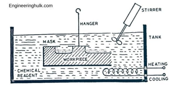
Chemical machining (CHM) removes material by controlled chemical dissolution: the areas to be kept are covered with a chemically resistant coating called a maskant, and the exposed areas are dissolved away by a reagent called an etchant. Metal is removed at roughly 0.02 to 0.04 mm per minute per exposed surface, with no cutting force, no tool wear and no burrs. It is one of the oldest non-traditional machining processes still in daily industrial use, and every printed circuit board is made by it.
Where chemical machining sits among non-traditional processes
Non-traditional machining processes are grouped by the energy they use to remove material. Chemical machining is the chemical family, alongside electrochemical machining (ECM), which adds an external current to speed up and steer the same kind of dissolution.
- Mechanical: ultrasonic machining, abrasive jet, water jet.
- Thermal: electric discharge machining (EDM), laser beam, electron beam, plasma arc.
- Chemical and electrochemical: chemical machining, photochemical machining, electrochemical machining.
The defining feature of CHM is that removal is area-based, not path-based. A cutter has to travel over every square millimetre it removes; an etchant attacks the whole exposed area at once. Etching a 2 metre wing skin panel takes the same time as etching a 100 mm coupon of the same alloy to the same depth, and a tank can hold dozens of parts at a time. That is the economics of the process in one sentence.
The variants: chemical milling, photochemical machining, blanking and engraving
Chemical milling
Chemical milling means etching pockets, channels and tapered sections into relatively thick parts, usually to remove weight while leaving stiffening ribs and lands. Depths run from a fraction of a millimetre up to about 12 mm, although most production work stays under 6 mm. The maskant is normally a thick peelable coating that can survive an hour or more in a hot etchant. This is the aerospace version of the process.
Photochemical machining (photoetching)
Photochemical machining (PCM), also called photoetching or photofabrication, uses a light-sensitive resist instead of a hand-cut mask. The pattern comes from a photographic tool, so feature accuracy is limited by optics rather than by a knife. PCM is for thin sheet, typically 0.02 to 2 mm thick, and for fine detail such as mesh, slots and hundreds of small holes.
Chemical blanking and chemical engraving
Chemical blanking is PCM taken all the way through the sheet, so the etch cuts the part out completely. It replaces a press tool for thin, delicate or short-run parts, with no burr and no distortion, which matters for spring steel shims and lead frames. Chemical engraving stops partway through and is used for nameplates, scales and instrument panels, often with the recess filled with paint afterwards.
Chemical machining process steps and the reason for each
- Cleaning and degreasing. The part is degreased and cleaned, chemically or by vapour. Any oil, oxide or fingerprint stops the maskant bonding and stops the etchant attacking evenly, and both faults show up as patchy depth later. This step decides the quality of everything after it.
- Masking. A chemically resistant coating is applied over the whole part by dipping, spraying, flow coating, screen printing or photoresist. The maskant must resist the etchant for the full immersion time without lifting at the edges.
- Scribing. For cut-and-peel work, the outline is cut through the maskant with a knife against a template, and the coating inside the outline is peeled away to expose the metal. In photoresist work this step does not exist, because exposure and development create the openings.
- Etching. The part is immersed in, or sprayed with, a heated and agitated etchant. Dissolution starts at the exposed surface and works downward. Time is the main control on depth; the part is removed when calculation and trial say the depth has been reached.
- Rinsing and demasking. The part is rinsed to stop the reaction, then the remaining maskant is stripped by peeling or in a chemical stripper. Residual etchant left under a mask edge keeps attacking the part, so the rinse is not a formality.
- Inspection. Depth is checked with a depth gauge, ultrasonic thickness meter or section, widths on an optical comparator, and the surface is inspected for pitting and unetched islands. Parts are usually stress-relieved or handled carefully, as removing material unbalances the residual stress in rolled plate and can bow a large panel.
Maskants compared
| Maskant type | How it is applied | Detail and accuracy | Cost | Best for |
|---|---|---|---|---|
| Cut and peel | Dip, spray or flow coat an elastomer (vinyl, neoprene or butyl), then scribe to a template and peel | Lowest. Edge accuracy depends on the operator’s knife; typically a few tenths of a millimetre | Lowest tooling cost, highest labour per part | Large parts, deep etching, small batches, chemical milling |
| Screen printed resist | Ink printed through a mesh screen carrying the pattern | Medium. Feature accuracy around 0.08 to 0.13 mm; the screen mesh limits fine detail | Moderate screen cost, fast per part | Medium volumes, shallow etching, nameplates and panels |
| Photoresist | Coat or laminate a light-sensitive film, expose through a photographic tool, develop away the exposed pattern | Highest. Feature accuracy down to about 0.01 to 0.05 mm, repeatable part to part | Highest setup cost, negligible cost per part at volume | Thin sheet, fine detail, high volume, PCM and PCB work |
One rule holds across all three: the maskant defines the geometry, so the process is only ever as accurate as the mask and the undercut behaviour beneath it.
Etchants used for different materials
| Workpiece material | Etchant type commonly used | What it suits |
|---|---|---|
| Carbon and alloy steels, stainless steel | Ferric chloride solution | The workhorse etchant for steels and for most photochemical machining. It is regenerable, works by spray, and is the standard choice for shims, lead frames and mesh. |
| Copper and copper alloys | Ferric chloride, or alkaline ammoniacal etchants in PCB production | Printed circuit board tracks, lead frames, contacts and EMI shielding parts. Alkaline systems suit continuous conveyorised lines. |
| Aluminium and its alloys | Sodium hydroxide (caustic) based solutions | Aerospace chemical milling of skin panels and extrusions. Fast and well understood, but it produces hydrogen and a metallic sludge that has to be managed. |
| Titanium and its alloys | Hydrofluoric acid with nitric acid | Aerospace titanium parts. The nitric addition is there to limit hydrogen pickup, which would otherwise embrittle the metal. |
| Nickel alloys and superalloys | Acid mixtures based on nitric and hydrochloric acids | Turbine hardware and thin superalloy details; slower etching and tighter process control. |
| Magnesium alloys | Nitric acid based solutions | Light alloy castings and panels. Magnesium etches fast, so timing is critical. |
These are the material families and reagent types described in standard machining texts and industry practice. Concentrations, additives and inhibitors are proprietary to each shop, and the real ones sit in a controlled process sheet, not in an article.
Etch rate, undercut and the etch factor
Metal dissolves outward in every direction the etchant can reach, not just downward. As soon as the etch front goes below the mask edge, it starts eating sideways under the mask. That sideways removal is called undercut, and it is the accuracy limit of the whole process.
Etch factor Fe = depth of cut (d) / undercut (u)
A perfectly isotropic attack would remove as much sideways as downward and give Fe = 1. Real combinations of material and etchant do better than that: values around 1.5 to 2 are usual for aluminium alloys, about 2 for low carbon steel and close to 1 for titanium alloys. A higher etch factor means a straighter wall and a smaller correction. Some textbooks and question banks write the ratio the other way up (undercut over depth), so check which convention a paper is using before you substitute numbers.
Worked example
An aluminium panel is to be chemically milled to a depth of 1.5 mm, and the material and etchant combination gives an etch factor of 2.0.
- Undercut u = d / Fe = 1.5 / 2.0 = 0.75 mm on each side.
- A pocket that must finish 60 mm wide will therefore open out by 0.75 mm at each edge, that is 1.5 mm in total.
- So the mask opening is scribed at 60 – 1.5 = 58.5 mm, and the template is cut to that dimension.
- At a typical etch rate of 0.025 mm/min, the immersion time is 1.5 / 0.025 = 60 minutes per surface.
Two practical points follow. Undercut is predicted, not eliminated, so the mask always carries the correction. And because undercut grows with depth, deep pockets have visibly sloped walls and the process loses accuracy as it goes deeper.
Process parameters and their effect
| Parameter | Effect of increasing it | Why it is controlled |
|---|---|---|
| Temperature | Etch rate rises steeply; reaction rates roughly double for every 10 degrees Celsius in many systems | The strongest single control on rate, and the strongest source of scatter. Tanks are heated and thermostatted, and a few degrees of drift changes the depth reached in a fixed time. |
| Etchant concentration | Rate rises up to a peak, then falls as dissolved metal builds up | The bath is loaded with metal as it works, so concentration and metal content are titrated on a schedule and the bath is topped up or regenerated. |
| Agitation | Faster and far more uniform etching | It replaces the spent, metal-rich layer sitting on the surface with fresh etchant, and clears hydrogen bubbles that otherwise mask spots. Done by pumping, air sparging, part movement or spray. |
| Immersion time | Depth increases, and so does undercut | Time is the operator’s control on depth, once temperature and concentration are fixed. |
| Material condition | Coarse grain, segregation, weld metal and porosity all etch unevenly | Decides the surface finish and whether the part is suitable at all. |
Accuracy, surface finish and materials
Typical capability, as a planning guide rather than a guarantee:
- Tolerance on depth in chemical milling: of the order of 10% of the etched depth, so a 1.5 mm pocket is held to roughly plus or minus 0.15 mm without special control.
- Tolerance in photochemical machining: around plus or minus 0.02 to 0.05 mm on thin sheet, and a minimum feature width of roughly one times the material thickness. Fine work is limited by that thickness-to-feature rule more than by anything else.
- Surface finish: commonly 0.8 to 6.3 micron Ra, depending on the material, its grain structure and the depth removed. Etched surfaces are matt and slightly textured, never polished.
- Suited materials: aluminium and magnesium alloys, carbon and stainless steels, copper alloys, titanium, nickel alloys, and, with suitable reagents, silicon, glass and some ceramics.
- Poorly suited: porous castings and powder-metallurgy parts (etchant gets inside and stays there), welded or heavily segregated material where different zones etch at different rates, and any part where a sharp internal corner or a deep narrow slot is essential.
Advantages and limitations
| Advantages | Limitations |
|---|---|
| No cutting force, no clamping distortion and no burrs, so very thin and delicate parts survive the process. | Material removal rate is low. A deep pocket takes hours, and depth is practically limited to about 12 mm. |
| No tool wear, and hardness of the work does not matter. | Undercut is unavoidable and grows with depth, so walls slope and tolerances widen. |
| Etches the whole exposed area at once, so large panels and many parts per batch cost little more than one. | Sharp internal corners cannot be produced; the corner radius tends towards the etch depth. |
| Low tooling cost and fast design changes, since the tool is a template or a photographic film, not a die. | Surface defects, segregation and porosity in the raw material are reproduced or made worse. |
| No heat-affected zone, no recast layer and no residual stress introduced by cutting. | Spent etchant, rinse water and metal sludge are regulated waste streams that must be treated. |
| Works on non-conductive materials, unlike EDM and ECM. | Skilled control of bath chemistry is needed for repeatable results. |
Chemical machining compared with EDM, laser and milling
| Factor | Chemical machining | EDM | Laser cutting | Conventional milling |
|---|---|---|---|---|
| Removal mechanism | Chemical dissolution | Spark erosion | Melting and vaporising | Shearing by a cutting edge |
| Cutting force | None | None | None | High, needs rigid clamping |
| Heat-affected zone | None | Recast layer present | Present, narrow | Minor, with coolant |
| Material limits | Must be chemically attackable; porous parts excluded | Must be electrically conductive | Most materials; reflective metals are harder | Hardness limits tool life |
| Typical tolerance | Plus or minus 0.02 to 0.05 mm on thin sheet | Plus or minus 0.005 to 0.025 mm | Plus or minus 0.05 to 0.1 mm | Plus or minus 0.02 to 0.05 mm |
| Burrs | None | None | Slight dross | Yes, deburring needed |
| Scales with area or with path | Area. Many parts at once | Path and area, slow | Path length | Path length |
| Best fit | Thin sheet detail, large shallow pockets, burr-free short runs | Hard material, deep cavities, sharp internal corners | Fast profile cutting of sheet, one-off to medium runs | Thick stock, deep and three-dimensional shapes |
Applications of chemical machining
- Aerospace skin panels. Aluminium wing and fuselage skins are chemically milled to leave thicker lands where the stress is and thinner fields elsewhere, taking weight out of a part far too large and too thin to mill mechanically without distortion.
- Printed circuit boards. The copper is masked by a photoresist matching the artwork and the rest is etched away, leaving the tracks. This is the same process at a smaller scale, and it is the version every reader has held in their hand.
- Lead frames and connectors for integrated circuit packaging, where thousands of fine, burr-free features are needed in thin copper alloy.
- Shims, washers, springs and laminations produced by chemical blanking, where a press would leave a burr or roll the edge over.
- Fine mesh, filters, screens and encoder discs, often etched from both sides at once to halve the time and control the wall shape.
- Decorative and instrument panels, nameplates, dials and scales produced by chemical engraving.
- Weight reduction and local thinning on missile bodies, launch vehicle components and satellite structures.
Safety and effluent handling
The reagents used in chemical machining are industrial hazardous chemicals. Hot alkali causes severe burns, acid mixtures release nitrogen oxide fumes, and hydrofluoric acid is a specific medical emergency because it penetrates skin and attacks bone calcium, with injuries that can be delayed and disproportionate to how they first look. Industrial practice controls this with engineering measures, not with care alone: closed or bunded tanks, local exhaust ventilation over every bath, fume scrubbers, interlocked temperature controls, emergency showers and eyewash stations at the line, full chemical personal protective equipment, and trained operators working to a written process sheet with the safety data sheet on hand.
The waste side is just as regulated. Spent etchant is neutralised and treated, dissolved metal is recovered or precipitated as sludge, rinse waters are treated before discharge, and the residues are handled as hazardous waste. In India this sits under the Hazardous and Other Wastes (Management and Transboundary Movement) Rules, 2016 and the effluent standards of the state pollution control boards. None of this scales down: chemical machining is a licensed industrial operation, and the article you are reading describes how it works, not a procedure anyone should attempt outside such a facility.
References
- AICTE Model Curriculum, Non-Traditional Machining (unit on chemical and electrochemical machining).
- Standard manufacturing technology texts on non-traditional machining, for etch factor definitions and typical etchant and maskant selections.
- Hazardous and Other Wastes (Management and Transboundary Movement) Rules, 2016, Ministry of Environment, Forest and Climate Change.
FAQs
What is the chemical machining process?
Chemical machining removes metal by controlled chemical dissolution. The part is cleaned, coated with a resistant maskant, the areas to be machined are exposed by scribing and peeling or by developing a photoresist, and the part is immersed in a heated, agitated etchant that dissolves the exposed metal. It is then rinsed, demasked and inspected. Removal runs at roughly 0.02 to 0.04 mm per minute per surface.
What is the difference between chemical milling and photochemical machining?
Chemical milling etches pockets and tapered sections into thicker parts, up to about 12 mm deep, using a thick cut-and-peel maskant scribed against a template. Photochemical machining works on thin sheet from about 0.02 to 2 mm, uses a photoresist exposed through photographic artwork, and produces far finer detail with tolerances near plus or minus 0.02 to 0.05 mm.
What is the etch factor in chemical machining?
The etch factor is the depth of cut divided by the undercut, Fe = d / u. It measures how straight the etched wall is. Values around 1.5 to 2 are typical for aluminium alloys and about 2 for low carbon steel. If a 1.5 mm deep pocket has an etch factor of 2.0, the undercut is 0.75 mm per side, so the mask opening is cut 1.5 mm narrower than the finished pocket.
Which etchants are used for which materials?
Ferric chloride solutions are the usual choice for steels and copper alloys, sodium hydroxide based solutions for aluminium, and hydrofluoric acid with nitric acid for titanium alloys. Nickel and superalloys use acid mixtures based on nitric and hydrochloric acids. Actual concentrations and additives are proprietary and are controlled inside licensed industrial facilities.
What are the limitations of chemical machining?
Low removal rate, a practical depth limit around 12 mm, unavoidable undercut that widens tolerances as depth increases, no sharp internal corners, sensitivity to porosity and segregation in the raw material, and hazardous etchants with regulated waste treatment. It is a process for thin, wide, burr-free work rather than for deep three-dimensional shapes.