A milling cutter is a rotating multi-tooth cutting tool used on a milling machine; each tooth takes a small chip as the workpiece is fed past the spinning cutter. The main types are plain (slab) cutters, side and face cutters, slitting saws, end mills, face mills, fly cutters and special cutters such as T-slot, Woodruff key-seat, dovetail, gear and thread mills. They are made of HSS or carbide, and are chosen by the surface to be cut, the work material and the machine.
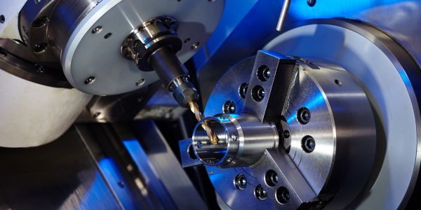
What is a milling cutter and how does it cut?
Unlike a lathe or shaper tool with one cutting edge, a milling cutter has many edges round its circumference or end. The cutter spins and the table carrying the work supplies the feed. Each tooth cuts for part of a revolution and cools for the rest, making a separate comma-shaped chip. Milling is one of the main material removal processes, and it produces flat faces, steps, slots, pockets, profiles, gears and threads.
Peripheral milling vs face milling
- Peripheral (plain) milling: the cutter axis is parallel to the machined surface and the teeth on the periphery do the cutting. Slab cutters on a horizontal milling machine work this way.
- Face milling: the cutter axis is perpendicular to the machined surface. The teeth on the periphery remove most of the metal, and the teeth on the face finish the surface. Face mills and end mills on a vertical machine work this way.
End milling is a mix of both: the side of an end mill cuts a wall (peripheral) while its end cuts the floor (face).
Up milling vs down (climb) milling
| Point | Up (conventional) milling | Down (climb) milling |
|---|---|---|
| Cutter rotation vs feed | Teeth move against the feed direction | Teeth move in the same direction as the feed |
| Chip thickness | Starts at zero, ends at maximum | Starts at maximum, ends at zero |
| Effect on the edge | Tooth rubs before it bites; more heat and wear, work-hardening on some steels | Tooth bites at once; less rubbing, longer tool life |
| Force on the work | Tends to lift the work off the table | Pushes the work down on the table |
| Surface finish | Poorer | Better |
| Machine needed | Works on old manual machines with lead screw backlash | Needs a backlash-free feed (ball screw, as on CNC); otherwise the cutter can pull the table in |
On a CNC machine, climb milling is the usual first choice. On a worn manual machine without a backlash eliminator, stick to up milling.
Types of milling cutters
| Cutter | Shape and teeth | Typical job |
|---|---|---|
| Plain (slab) cutter | Cylinder with teeth on the periphery only; straight teeth for light cuts, helical teeth for heavy cuts | Wide flat surfaces on a horizontal machine |
| Side and face cutter | Disc with teeth on the periphery and both sides | Steps, slots, straddle milling (two cutters on one arbor) and gang milling |
| Staggered-tooth cutter | Side cutter whose teeth alternate in helix direction | Deep, narrow slots, with better chip clearance and less chatter |
| Slitting saw | Thin plain cutter, sides relieved (dished) for clearance | Cutting off stock and sawing narrow slots |
| End mill: flat | Shank cutter with teeth on the end and sides, square corners | Slots, pockets, shoulders, profiles |
| End mill: ball-nose | Hemispherical end | 3D contoured surfaces such as dies and moulds |
| End mill: bull-nose | Flat end with a corner radius | Pockets with a filleted floor; the radius also protects the corner from chipping |
| Face mill | Large body carrying indexable carbide inserts | Facing large flat areas at high metal removal rates |
| Fly cutter | Bar holding one or two single-point tools | Light facing with a good finish; cheap tool for small shops |
| T-slot cutter | Small disc with side teeth on a narrow neck | The wide lower part of T-slots, after the vertical slot is cut |
| Woodruff key-seat cutter | Small shank-type disc cutter | Semicircular seats for Woodruff keys in shafts |
| Dovetail cutter | Angled cone, commonly 45 or 60 degrees | Dovetail slides and ways |
| Form cutters: gear, concave, convex | Teeth ground to the exact profile needed | Gear teeth (involute cutters), convex edges (concave cutter), grooves (convex cutter) |
| Thread mill | Teeth shaped like the thread form | Internal and external threads by helical interpolation on CNC |
A note on gear cutters
An involute gear cutter matches the tooth space of one module, but the ideal profile also changes with the number of teeth. Workshops therefore use a set of eight cutters per module, each covering a range of tooth numbers, with the work indexed tooth by tooth using a dividing head.
Milling cutter materials and coatings
- High-speed steel (HSS): tough and easy to regrind. Grades such as M2, and cobalt grades such as M42 for tougher work. Used at low cutting speeds on manual machines and for form cutters.
- Solid carbide: tungsten carbide in a cobalt binder. Much harder and able to run several times faster than HSS, but brittle, so it needs a rigid machine and holder. Most CNC end mills are solid carbide.
- Indexable carbide inserts: clamped in a steel body (face mills, shoulder mills). When an edge wears, the insert is turned to a fresh edge instead of regrinding the cutter.
- Coated carbide: a thin hard layer on carbide or HSS. TiN (gold colour) is a general-purpose coating; TiAlN and AlTiN resist heat better and suit dry or high-speed cutting of steel. Uncoated or specially coated sharp tools are often used for aluminium, since some coatings let aluminium stick.
- CBN and PCD: cubic boron nitride for hardened steel and cast iron; polycrystalline diamond for aluminium, copper alloys and composites. PCD is not used on steel, because the carbon in diamond reacts with iron at cutting temperatures.
Cutter geometry: flutes, helix and rake
- Number of flutes (teeth): fewer flutes leave more room for chips. Two or three flutes are common for aluminium and slotting; four or more for steel, where chips are smaller and more teeth give a higher feed rate.
- Helix angle: a helical tooth enters the cut gradually, so the cut is smoother than with straight teeth. Around 30 degrees is a common general-purpose helix; higher helix angles lift chips out faster and are often used for aluminium. Variable-helix end mills break up the rhythm that causes chatter.
- Rake angle: positive rake gives a sharper, free-cutting edge for soft and ductile metals. Negative rake gives a stronger edge, used on carbide face mills for hard materials and interrupted cuts.
Speed, feed and metal removal rate formulas
- Spindle speed: N = 1000 V / (π D) rpm, where V is cutting speed (m/min) and D is cutter diameter (mm).
- Table feed: F = fz x z x N mm/min, where fz is feed per tooth (mm) and z is the number of teeth.
- Metal removal rate: MRR = ae x ap x F mm3/min, where ae is the radial width of cut and ap the axial depth of cut (mm).
Worked example: speed and feed for a carbide end mill
A 16 mm, 4-flute carbide end mill cuts mild steel at V = 120 m/min with fz = 0.05 mm per tooth. It takes a side cut with radial width ae = 8 mm and axial depth ap = 10 mm. (These cutting values are illustrative; take real starting values from the tool maker’s catalogue.)
- Spindle speed N = 1000 x 120 / (π x 16) = 120,000 / 50.27 = 2,387 rpm
- Table feed F = 0.05 x 4 x 2,387 = 477 mm/min (477.5 before rounding)
- MRR = 8 x 10 x 477.5 = 38,200 mm3/min = 38.2 cm3/min
- Time for a 200 mm long pass, adding the cutter diameter for approach and exit: (200 + 16) / 477.5 = 0.452 min, about 27 seconds
Student tip: if the machine’s nearest speed is lower, say 2,000 rpm, recalculate the feed with that speed (0.05 x 4 x 2,000 = 400 mm/min). Keeping feed per tooth constant is what protects the edge.
How to choose a milling cutter
| Job | Usual first choice |
|---|---|
| Large flat face on a CNC mill | Indexable face mill, diameter about 1.3 to 1.5 times the cut width (a common rule of thumb) |
| Wide flat surface on a horizontal manual mill | Helical slab cutter |
| Pockets, shoulders, profiles | Flat or bull-nose end mill |
| 3D mould or die surface | Ball-nose end mill |
| Keyway in a shaft | End mill (sunk key) or Woodruff cutter (Woodruff key) |
| Deep narrow slot | Staggered-tooth side cutter or slitting saw |
| Gear teeth, one-off | Involute form cutter with a dividing head |
| Threads larger than available taps, or in costly parts | Thread mill on CNC |
Beyond the shape, check the work material (sets tool material and flute count), the machine’s rigidity and power, and the shortest tool length that will reach, since a long overhang is the most common cause of chatter.
Milling cutter wear and failure
- Flank wear: a worn land on the clearance face; the normal, gradual end of tool life. A common criterion is an average flank wear land of about 0.3 mm.
- Crater wear: a hollow worn into the rake face by hot chips at high speed.
- Chipping and fracture: small or large pieces break off the edge, usually from too high a feed, chatter, or a hard spot or scale.
- Thermal cracking: cracks across the edge of carbide from repeated heating in the cut and cooling out of it. Intermittent coolant makes it worse, which is why many carbide milling jobs run dry or with air blast.
- Built-up edge: work material welding onto the edge, common with aluminium and low-carbon steel at low speed. Raising speed or using a sharper, polished tool helps.
How the chip forms, and why it curls or breaks, is covered in our page on types of chips in metal cutting. For other workshop machines, see shaper machines, drilling machines and CNC machines. The NPTEL manufacturing processes courses cover milling theory in more depth.
FAQs
What is a milling cutter?
A milling cutter is a rotating tool with several cutting teeth used on a milling machine. Each tooth removes a small chip as the work is fed past the cutter, producing flat surfaces, slots, pockets and profiles.
What are the main types of milling cutters?
Plain (slab) cutters, side and face cutters, staggered-tooth cutters, slitting saws, end mills (flat, ball-nose, bull-nose), face mills, fly cutters, T-slot cutters, Woodruff key-seat cutters, dovetail cutters, form cutters such as gear cutters, and thread mills.
What is the difference between up milling and down milling?
In up milling the cutter teeth move against the feed and the chip starts thin. In down (climb) milling the teeth move with the feed and the chip starts thick, giving better finish and tool life, but it needs a backlash-free machine.
How do you calculate spindle speed for a milling cutter?
Use N = 1000 V / (π D). For a 16 mm cutter at 120 m/min, N = 1000 x 120 / (π x 16) = 2,387 rpm. The table feed is then F = feed per tooth x number of teeth x N.
What material are milling cutters made of?
Mostly high-speed steel or tungsten carbide, often coated with TiN or TiAlN. CBN is used for hardened steel and PCD for aluminium and composites.