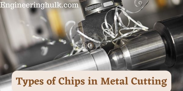
Metal cutting produces three classic types of chips: continuous chips, discontinuous chips, and continuous chips with a built-up edge (BUE). A fourth type, serrated or segmented chips, forms when cutting titanium alloys and hardened steels. Which one you get depends mainly on how ductile the work material is, the cutting speed, the rake angle of the tool, the feed and depth of cut, and friction at the tool face, including whether a cutting fluid is used. The chip type is a quick visual check on how well the cut is going.
How a chip forms
In orthogonal cutting, the tool’s wedge pushes into the work and the layer ahead of it is sheared along a narrow zone called the shear plane, inclined at the shear angle φ to the direction of cut. The sheared metal then slides up the rake face of the tool as the chip. Whether that chip stays in one piece, breaks up, sticks to the tool or shears in bands decides its type.
1. Continuous chips
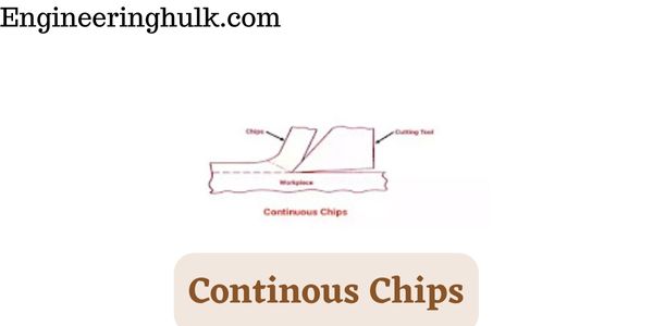
A continuous chip is a long, unbroken ribbon with a smooth, shiny underside (where it rubbed the rake face) and a rough upper side. The metal shears steadily along the shear plane without fracturing.
Produced by: ductile materials such as low-carbon steel, aluminium and copper; high cutting speed; large positive rake angle; small feed and depth of cut; a sharp tool with a smooth rake face; and good cutting fluid to reduce friction.
Effect: the best surface finish and steady cutting forces, so tool life is usually good. The drawback is chip handling: long ribbons tangle round the work and tool, can cut the operator, and jam automatic machines. That is why continuous chips are usually broken deliberately with a chip breaker.
2. Discontinuous chips
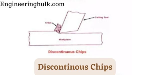
Discontinuous chips are small separate fragments. The metal in the shear zone fractures instead of flowing, so each segment breaks off as it forms.
Produced by: brittle materials such as grey cast iron and some brasses and bronzes, and also by ductile materials cut under poor conditions: very low speed, large feed and depth of cut, small or negative rake angle, high friction at the tool face, and no cutting fluid.
Effect: easy to handle and clear away, which suits automatic machines. With brittle materials the finish is acceptable and it is the normal chip. With ductile materials it is a warning sign: the cutting force rises and falls with each fragment, which causes vibration, a rougher surface and faster tool wear.
3. Continuous chips with built-up edge (BUE)
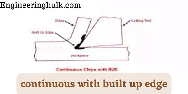
Under high pressure and temperature at the tool tip, small particles of the work material weld onto the cutting edge and work-harden. This lump, the built-up edge, acts as a false cutting edge. It grows, becomes unstable and breaks off, partly with the chip and partly onto the machined surface, and then starts growing again.
Produced by: ductile materials that work-harden and tend to stick, such as low-carbon steel and aluminium alloys; low to moderate cutting speeds; small rake angle; large feed; high friction; and no or poor cutting fluid.
Effect: poor surface finish, because the fragments that break off are left on the work, and poor dimensional control, because the BUE changes the effective tool shape. When BUE fragments break away they can pull tool material with them, so tool life also suffers. Raising the cutting speed, increasing the rake angle, polishing the rake face, and using a good cutting fluid or a coated tool reduce or remove BUE.
4. Serrated (segmented) chips
Serrated chips look like a continuous chip with a saw-tooth upper edge. They are semi-continuous: the chip is held together, but deformation is concentrated in narrow, intensely sheared bands between segments.
Produced by: materials with low thermal conductivity and strength that falls sharply with temperature, above all titanium alloys, nickel-based superalloys and hardened steels, especially at higher cutting speeds. Heat generated in the shear zone cannot escape, so the metal softens locally and shears in a narrow band (adiabatic shear), then the next segment begins.
Effect: the cutting force fluctuates at high frequency, which can cause chatter and edge chipping. Heat stays near the tool edge, so tool wear is fast. Rigid set-ups, sharp tools with suitable coatings, high-pressure coolant and carefully chosen speeds are used to control them.
Which conditions give which chip
| Chip type | Work material | Cutting speed | Rake angle | Feed and depth | Friction / cutting fluid | Finish | Tool life |
|---|---|---|---|---|---|---|---|
| Continuous | Ductile | High | Large positive | Small | Low friction, good fluid | Best | Good |
| Discontinuous | Brittle (or ductile under poor conditions) | Low | Small or negative | Large | High friction, no fluid | Fair on brittle, poor on ductile | Fair; worse on ductile |
| Continuous with BUE | Ductile, work-hardening | Low to moderate | Small | Large | High friction, poor fluid | Poor | Reduced |
| Serrated | Low thermal conductivity, hard (Ti, Ni alloys, hardened steel) | Moderate to high | Varies | Varies | High-pressure coolant helps | Fair | Short |
Chip thickness ratio and shear angle
The chip is always thicker than the layer it was cut from, because the metal is compressed and sheared. Two quantities describe this in orthogonal cutting:
Chip thickness ratio: r = t / tc, where t is the uncut chip thickness (depth of the layer removed) and tc is the measured chip thickness. Since tc > t, r is less than 1. Its inverse, 1/r, is called the chip reduction coefficient.
Shear angle: tan φ = r cos α / (1 – r sin α), where α is the rake angle.
A larger r (thinner chip) means a larger shear angle, a shorter shear plane, less energy per unit volume, and usually a better, continuous chip.
Worked example
Problem: In orthogonal turning of mild steel with a tool of rake angle α = 10°, the uncut chip thickness is 0.25 mm and the measured chip thickness is 0.625 mm. The cutting speed is 120 m/min. Find the chip thickness ratio, shear angle, shear strain and chip velocity.
- Chip thickness ratio: r = 0.25 / 0.625 = 0.40.
- cos 10° = 0.9848 and sin 10° = 0.1736.
- tan φ = (0.40 × 0.9848) / (1 – 0.40 × 0.1736) = 0.3939 / 0.9305 = 0.4233.
- Shear angle: φ = tan-1(0.4233) = 22.9°.
- Shear strain: γ = cot φ + tan(φ – α) = 2.362 + tan 12.9° = 2.362 + 0.230 = 2.59.
- Chip velocity: Vc = r × V = 0.40 × 120 = 48 m/min.
A chip thickness ratio of 0.4 (the chip is 2.5 times thicker than the cut) is typical of mild steel at moderate speed. If a better cutting fluid lowered friction so that tc fell to 0.5 mm, r would rise to 0.5 and the shear angle to about 28.3r would rise to 0.5 and the shear angle would increase, reducing the cutting force.deg;, reducing the cutting force.
Chip breakers and why chip control matters
Chip control means making chips break into short, predictable pieces. It matters because:
- Safety: long continuous chips are sharp and hot and can wrap round the chuck and cut hands.
- Surface finish: a tangled chip can scratch the finished surface.
- Automation: CNC lathes and unmanned cells need chips that fall away and can be carried off by a conveyor; a bird’s nest of swarf stops the machine.
- Tool and machine protection: chips caught between the tool and work can chip the edge.
- Handling and recycling: short chips pack densely and are easier to collect and sell as scrap.
A chip breaker curls the chip more tightly than it would naturally curl, so it strains and snaps. Common types:
- Groove type: a groove ground or moulded into the rake face behind the cutting edge. Almost all modern indexable carbide inserts have moulded chip-breaker geometries designed for particular feed and depth ranges.
- Step (obstruction) type: a step ground on the rake face, so the chip hits a wall and curls.
- Clamp-on type: a separate plate clamped on the tool, adjustable for different conditions.
Increasing the feed also makes chips thicker and easier to break, which is why chip breakers are specified for a feed range.
Chip colour as a temperature indicator
When steel is cut, its chip surface oxidises according to its temperature, much like the temper colours seen when heat-treating. Bright, silvery chips mean the chip stayed relatively cool; straw or golden chips mean it was hotter; blue and then purple or dark chips mean it was hotter still. With high-speed steel tools, blue chips often mean the speed is too high for the tool. With carbide tools, blue chips on steel are common at productive speeds, because most of the heat leaves with the chip. Colour is only a rough guide; it also depends on the fluid used and the time the chip spends in air.
For machine context, see our pages on lathe machine parts, shaper machines and milling cutters, and for ductility and hardness, mechanical properties of materials.
FAQs
What are the types of chips in machining?
Continuous chips, discontinuous chips and continuous chips with built-up edge are the three classic types. Serrated or segmented chips are a fourth type, seen with titanium alloys, nickel alloys and hardened steels.
When are discontinuous chips formed?
When cutting brittle materials such as cast iron, and when cutting ductile materials at low speed with large feed, small or negative rake angle, high friction and no cutting fluid.
Which type of chip gives the best surface finish?
The continuous chip, formed with ductile materials at high speed, positive rake and low friction. It needs a chip breaker so it does not tangle.
How can built-up edge be reduced?
Increase cutting speed, use a larger positive rake angle, polish or coat the tool face, and use a good cutting fluid to reduce friction and welding at the tool tip.
What is the chip thickness ratio?
The ratio of uncut chip thickness to actual chip thickness, r = t / tc. It is always less than 1 and is used to find the shear angle: tan φ = r cos α / (1 – r sin α).