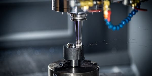
A shaper (shaping machine) is a machine tool in which a single-point cutting tool, held on a reciprocating ram, moves back and forth in a straight line over a stationary workpiece and cuts only on the forward stroke. After each stroke the table feeds the work sideways by a small amount, so the tool planes off a series of strips to produce a flat surface. A quick-return mechanism makes the idle return stroke faster than the cutting stroke to save time.
How a shaper machine works
The ram carries the tool forward across the work (the cutting stroke), removing a thin layer of metal. It then pulls the tool back (the return stroke) without cutting. During the return stroke the table moves across by the feed, usually a fraction of a millimetre to a few millimetres, ready for the next cut. Depth of cut is set by lowering the tool slide. Because cutting is intermittent, a shaper removes metal slowly, but it needs only a cheap single-point tool and simple set-ups.
Main parts of a shaper
| Part | Description and job |
|---|---|
| Base | Heavy cast-iron foundation bolted to the floor; absorbs cutting forces and vibration |
| Column | Hollow box casting on the base; houses the drive and quick-return mechanism; carries the ram guideways on top and the cross-rail guideways on its front face |
| Cross rail | Slides up and down the column face to set table height; carries the saddle |
| Saddle | Moves sideways along the cross rail to give the cross feed |
| Table | Box-shaped casting bolted to the saddle, with T-slots on its top and sides for clamping the work or a vice |
| Ram | Reciprocating member sliding in guides on top of the column; its stroke length and position are adjustable |
| Tool head | Fixed to the front of the ram; holds the tool; has a down-feed screw, a swivel base for angular cuts and the apron with the clapper box |
Why the clapper box lifts on the return stroke
The tool post is mounted on a clapper block hinged at its top inside the clapper box on the apron. On the cutting stroke the cutting force pushes the block back against the box, so the tool is held rigidly. On the return stroke the tool drags backwards over the freshly cut surface, and the hinge lets the clapper block swing up so the tool rides lightly over the work instead of digging in. This protects the cutting edge from chipping and the surface from scoring. For vertical and angular cuts, the apron is swivelled away from the surface being cut so that the tool swings clear of the work as it lifts.
Classification of shaper machines
| Basis | Types | Notes |
|---|---|---|
| Driving mechanism | Crank (crank and slotted link), hydraulic, geared (rack and pinion) | Crank shapers are the most common; hydraulic shapers give a constant cutting speed and smooth reversal |
| Position and travel of ram | Horizontal, vertical (slotter), travelling-head | A travelling-head shaper moves its ram and head along the bed to machine long, heavy work that stays still |
| Direction of cutting stroke | Push-cut (standard), draw-cut | A draw-cut shaper cuts as the ram moves towards the column, pulling the tool; suits heavy cuts with less vibration |
| Table design | Plain (standard), universal | A universal table can swivel and tilt, so angular surfaces can be cut without re-clamping |
A shaper’s size is given by its maximum stroke length, for example a 450 mm or 600 mm shaper.
Shaper mechanism: crank and slotted link quick return
In a crank shaper, a bull gear inside the column carries a crank pin with a sliding block. The block slides in a slotted lever that pivots at its lower end, and the top of the lever is linked to the ram. As the bull gear turns at constant speed, the slotted lever rocks back and forth and drives the ram.
The ends of the stroke occur when the crank is at right angles to the slotted lever. The crank turns through a large angle during the forward (cutting) stroke and a smaller angle during the return stroke. Since the bull gear turns at constant speed, time is proportional to angle, so the return is quicker. If r is the crank radius and C the distance between the bull gear centre and the lever pivot, half the return angle γ is given by cos γ = r / C.
Stroke length is changed by altering the crank radius (moving the crank pin block along the bull gear slot), and stroke position by moving the ram relative to its connection with the lever.
In a hydraulic shaper, an oil pump drives a piston connected to the ram. Cutting speed stays constant along the stroke, and the return is quicker because the oil acts on the smaller side of the piston.
Worked example 1: quick-return ratio from crank geometry
A crank shaper has crank radius r = 85.5 mm and distance between the bull gear centre and slotted lever pivot C = 250 mm.
- cos γ = r / C = 85.5 / 250 = 0.342, so γ = 70.0°
- Return stroke angle = 2γ = 140°
- Cutting stroke angle = 360 – 140 = 220°
- Ratio of cutting time to return time = 220 / 140 = 1.57
- m = return time / cutting time = 140 / 220 = 0.636
Worked example 2: cutting speed and machining time
Cutting speed on a shaper uses the cutting stroke only:
V = L N (1 + m) / 1000 m/min, where L = stroke length (mm), N = double strokes per minute and m = return time / cutting time.
A mild steel plate 250 mm long and 150 mm wide is to be shaped on this machine. Allow 25 mm approach and overrun at each end, so L = 250 + 2 x 25 = 300 mm. Run at N = 30 strokes/min with a feed of 0.5 mm per stroke.
- Cutting speed V = 300 x 30 x (1 + 0.636) / 1000 = 14.7 m/min
- Number of strokes to cover the width = 150 / 0.5 = 300 strokes
- Machining time for one pass = 300 / 30 = 10 minutes
Check with the combined formula T = L b (1 + m) / (1000 V f) = 300 x 150 x 1.636 / (1000 x 14.73 x 0.5) = 10.0 minutes. Without quick return (m = 1), the same cutting speed would need a slower stroke rate and the job would take longer.
Operations done on a shaper
- Horizontal flat surfaces: the basic job, with the table fed sideways.
- Vertical surfaces: tool fed downwards by the tool slide, apron swivelled clear.
- Angular (inclined) surfaces: tool head swivelled to the required angle.
- Keyways and slots: external keyways on shafts and slots in blocks; internal keyways need a slotter.
- Grooves, splines and dovetails: with formed tools and an indexing attachment.
- Irregular and contoured surfaces: by combining feeds by hand or with a copying attachment.
The single-point tool cuts in the same way as a lathe tool, so the chip forms follow the same rules; see our page on types of chips in metal cutting.
Shaper vs planer vs slotter
| Point | Shaper | Planer | Slotter |
|---|---|---|---|
| What moves | Tool reciprocates; work is fed | Work (on table) reciprocates; tool is fed | Tool reciprocates vertically; work is fed |
| Work size | Small to medium | Large and heavy (beds, frames) | Small to medium |
| Ram direction | Horizontal | Table moves horizontally | Vertical |
| Tools | One tool at a time | Several tool heads can cut at once | One tool at a time |
| Typical jobs | Flat surfaces, external keyways, slots | Long flat surfaces, machine beds and guideways | Internal keyways, internal splines, internal profiles |
Why shapers are rare in industry today
Production shops have largely replaced shapers with milling machines and CNC machining centres. A milling cutter has many teeth cutting continuously, so it removes metal many times faster, and CNC mills produce flat faces, slots and pockets with no idle return stroke. Internal keyways are now usually made by broaching or on CNC slotting and wire-cut machines. Surface finishing is done by grinding; see our guides on milling cutters and grinding machines.
Shapers remain in tool rooms, repair shops and college workshops because they are cheap, use a simple tool that can be ground by hand, and are ideal for one-off jobs. They are still part of the B.Tech workshop and manufacturing processes syllabus in the AICTE model curriculum, and the quick-return mechanism is a standard kinematics of machines topic. Related workshop machines are covered in our page on drilling machines.
FAQs
What is a shaper machine?
A machine tool in which a single-point tool on a reciprocating ram cuts on the forward stroke across stationary work, which is fed sideways after each stroke. It produces flat, vertical, angular surfaces and slots.
What is the classification of shaper machines?
By drive: crank, hydraulic and geared. By ram travel: horizontal, vertical (slotter) and travelling-head. By cutting stroke: push-cut and draw-cut. By table: plain and universal.
Which mechanism is used in a shaper?
Most shapers use the crank and slotted lever quick-return mechanism. Hydraulic shapers use an oil-driven piston instead, which gives a constant cutting speed.
What is the function of the clapper box in a shaper?
It lets the tool hinge upward on the return stroke so it slides over the work instead of dragging, which protects the cutting edge and the machined surface.
What is the quick return ratio of a shaper?
It is the ratio of cutting-stroke time to return-stroke time, equal to the ratio of the crank angles. For a cutting angle of 220 degrees and a return angle of 140 degrees, the ratio is 220 / 140 = 1.57.