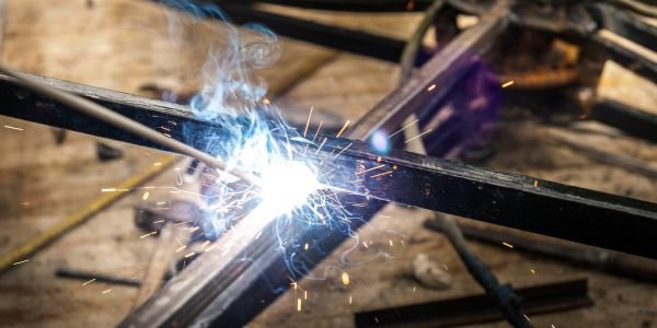
Stick welding is shielded metal arc welding (SMAW): an electric arc is struck between a flux-coated consumable electrode and the workpiece, the arc melts both, and the burning flux produces a shielding gas plus a slag blanket that protect the molten pool from air. The electrode is the filler metal, so it is consumed as you weld and replaced every 300 to 450 mm of stick. No gas cylinder is needed, which is why stick welding still owns outdoor and site work.
This page covers what is specific to the process: the coating, the machines, polarity, electrode codes, amperage, technique in all four positions, electrode storage and the defects you will actually meet. For the non-consumable, inert-gas alternative see TIG welding.
Why it is called stick welding, and its other names
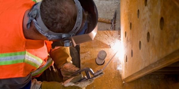
The consumable comes as a straight, rigid stick of wire coated in dried flux, so welders have always called it stick welding. The same process has several formal names, and they all mean one thing.
- SMAW, shielded metal arc welding, is the American Welding Society term and the one used in codes and procedure sheets.
- MMAW or MMA, manual metal arc welding, is the British and Indian term, and the one used in Bureau of Indian Standards documents.
- Arc welding on a workshop floor almost always means this process, although strictly it covers MIG, TIG and submerged arc as well.
- Electrode welding or rod welding is the shop-floor shorthand in many Indian fabrication units.
What the flux coating actually does
Strip the coating off and you have a bare wire that will strike an arc and lay down porous, brittle metal. Everything that makes the process work is in that coating, and it performs five jobs at once.
| Job | How the coating does it |
|---|---|
| Shielding gas | Cellulose and carbonates in the coating burn and decompose in the arc, releasing carbon dioxide and carbon monoxide. That gas column pushes air, and therefore oxygen and nitrogen, away from the arc and the molten pool. |
| Slag blanket | Mineral constituents melt and float on top of the weld pool, then freeze over the bead. The slag keeps air off the metal while it is still hot, slows the cooling rate, shapes the bead profile and, in vertical and overhead work, physically supports the pool while it solidifies. |
| Arc stabilisers | Potassium, sodium and titanium compounds have a low ionisation potential, so they keep the arc column conductive. This is what lets an electrode restrike itself 100 times a second on AC, where the current passes through zero on every half cycle. |
| Deoxidisers and alloying | Manganese and silicon scavenge oxygen out of the pool. Other coatings carry chromium, nickel, molybdenum or carbon into the deposit, so the weld metal chemistry can be set by the coating rather than by the core wire. |
| Arc direction and deposition rate | The coating burns back a little slower than the core, leaving a small cup at the tip that points the arc into the joint. Iron powder added to the coating melts into the pool and raises the amount of metal deposited per electrode. |
The coating is also the reason stick welding tolerates rust, mill scale and paint far better than gas-shielded processes: the slag absorbs a lot of the resulting contamination and floats it out.
Stick welding equipment
| Item | What to know |
|---|---|
| Transformer set (AC) | The simplest and cheapest machine. Steps mains voltage down to a welding voltage with a high current output, and gives AC only. Open circuit voltage is typically 70 to 80 V, which is what AC electrodes need to restrike. Heavy, tolerant of abuse, no electronics to fail. |
| Transformer-rectifier set (DC) | A transformer followed by a rectifier bridge, so the output is DC and either polarity can be selected at the terminals. Smoother arc than AC and suits electrodes that are DC only. |
| Inverter set | Switches the incoming supply at high frequency, so the transformer can be tiny. A 200 A inverter weighs 5 to 15 kg against 80 kg or more for the equivalent transformer. Inverters also give arc force (dig), hot start and anti-stick control, which makes low-hydrogen electrodes far easier to run. |
| Engine-driven generator | A diesel or petrol engine driving a welding generator. Standard on pipelines, bridges and any site without a usable mains supply. |
| Electrode holder | An insulated spring or screw clamp rated in amperes. It must grip the bare end of the electrode firmly at several angles, and it must stay cool enough to hold. |
| Work return (earth) clamp | Completes the circuit. Clamp it on clean bare metal as close to the joint as practical. A poor earth causes a wandering arc, overheating at the clamp and, on DC, worse arc blow. |
| Welding cables | Sized for current and for total length. Long, thin cables drop voltage and make the arc hard to strike, and welders blame the machine. |
| Chipping hammer and wire brush | Not accessories. Slag must come off completely between every run, and this is the tool that does it. |
| Electrode oven or quiver | A heated cabinet for low-hydrogen electrodes and a portable heated quiver to take them to the joint. Details further down. |
| Protection | A welding helmet with the shade suited to the current, usually shade 10 to 13 for stick work, plus leather gauntlets, a leather apron or jacket and dry footwear. Stick welding throws more spatter than gas-shielded processes, so cover skin properly. |
Duty cycle, and why a 200 A machine is not a 200 A machine
Duty cycle is the proportion of a ten-minute period for which the set can deliver a stated current without overheating. The ten-minute basis comes from IEC 60974-1. A set rated 200 A at 60% can weld for six minutes at 200 A and then needs four minutes to cool, inside every ten-minute block. The same machine will usually run 100% duty at a lower current, perhaps 150 A.
Stick welding is forgiving here, because changing electrodes, chipping slag and repositioning already give the machine its rest. A welder rarely exceeds about 50% arc-on time by hand.
Polarity in stick welding: DCEN, DCEP and AC
| Setting | Connection | Effect in SMAW | Typical use |
|---|---|---|---|
| DCEP (DC electrode positive, reverse polarity) | Electrode to +, work to − | The deepest penetration and the most stable arc. Preferred for low-hydrogen and cellulosic electrodes. | E6010 root runs, E7018 structural and pressure work, most code welding |
| DCEN (DC electrode negative, straight polarity) | Electrode to −, work to + | Faster melt-off of the electrode and a higher deposition rate, but shallower penetration. | Thin sheet and sheet-metal fabrication with rutile and iron-powder electrodes, where burn-through is the risk |
| AC | Alternating, no fixed polarity | Penetration between the two. Cures magnetic arc blow completely, and the cheapest machines give only this. Needs electrodes whose coating carries arc stabilisers. | E6011, E6013, AC-rated E7018, and any job where a DC arc keeps blowing sideways |
Note the reversal if you have come from TIG. In TIG, electrode negative puts most of the heat into the plate and gives the deepest penetration. In stick welding the rule is the other way round: DCEP penetrates deeper, because the coating chemistry and the transfer of molten metal across the arc dominate the simple heat split. Learn each process’s rule separately rather than carrying one across.
AWS A5.1 electrode classification decoded digit by digit
Carbon steel covered electrodes are classified in AWS A5.1/A5.1M, whose current edition is the 2025 one. Take E7018 and read it one character at a time.
- E: a covered electrode for shielded metal arc welding.
- 70: the minimum tensile strength of the deposited weld metal in thousands of pounds per square inch. 70 means 70,000 psi, about 483 MPa. A 60 in E6013 means 60,000 psi, about 414 MPa. Where the strength runs to three figures, as in E11018, the first three digits carry it.
- 1: the welding positions the electrode is approved for. 1 = all positions; 2 = flat and horizontal fillet only; 4 = all positions including vertical down.
- 8: the last digit, read together with the position digit, gives the coating type and the current and polarity it runs on. For 18 that is a low-hydrogen potassium coating with iron powder, run on DCEP or AC.
Optional suffixes follow a hyphen: -1 for improved impact toughness, R for a moisture-resistant coating, and H4, H8 or H16 for a guaranteed maximum diffusible hydrogen of 4, 8 or 16 ml per 100 g of deposited metal. An E7018-1 H4R is therefore a tougher, low-moisture, very low hydrogen version of the standard rod.
| Electrode | Coating | Current | Penetration | Where it is used |
|---|---|---|---|---|
| E6010 | High cellulose sodium | DCEP only | Deep, digging arc | Pipeline and pipe root runs (stovepipe welding), and dirty, rusty, painted or galvanised steel. Thin friable slag, fast-freezing pool. |
| E6011 | High cellulose potassium | AC or DCEP | Deep | The E6010 substitute for anyone with only an AC transformer. Same digging arc, same tolerance of poor surfaces, more spatter. |
| E6013 | High titania (rutile) potassium | AC, DCEP or DCEN | Shallow to medium | The general-purpose electrode of most Indian workshops. Soft quiet arc, neat bead, slag that peels off. Sheet, light fabrication, grilles, gates and training. |
| E7018 | Low hydrogen potassium with iron powder | DCEP or AC | Medium | Structural steelwork, thick sections, pressure parts, restrained joints and anything carrying a code. Tough, low-hydrogen deposit, but the coating must be kept dry. |
| E7024 | Iron powder titania, heavy coating | AC, DCEN or DCEP | Shallow to medium | High deposition flat and horizontal fillet work only, which is why its position digit is 2. Fast fill on thick plate. |
The Indian equivalent: IS 814 electrode coding
India classifies covered electrodes for carbon and carbon-manganese steel under IS 814:2004. The code is a letter-and-digit string rather than a four-digit number, and it carries more information than the AWS code does. The order fixed by the standard is:
E → covering letter → strength digit → elongation and impact digit → position digit → current and voltage digit → optional suffixes
| Position in the code | Values and meanings |
|---|---|
| Prefix E | A covered electrode for manual metal arc welding, made by extrusion. |
| Covering letter | A = acid, B = basic, C = cellulosic, R = rutile, RR = rutile heavy coated, SB = semi-basic. |
| Strength digit | 4 = ultimate tensile strength 410 to 540 MPa with 330 MPa minimum yield; 5 = 510 to 610 MPa with 400 MPa minimum yield. |
| Elongation and impact digit | 0 to 6, pairing a minimum percentage elongation with a minimum impact energy at a stated test temperature. In the 410 to 540 MPa range, for example, 1 is 20% with 47 J at +27 °C, 2 is 22% with 47 J at 0 °C and 3 is 24% with 47 J at −20 °C. The codes for the higher strength range follow the same idea at colder test temperatures. |
| Position digit | 1 = all positions; 2 = all positions except vertical down; 3 = flat butt, flat fillet and horizontal or vertical fillet; 4 = flat butt and flat fillet only; 5 = vertical down plus the positions in 3; 6 = any other position or combination. |
| Current and voltage digit | 0 = direct current only. Then the digits run in threes by minimum AC open circuit voltage: 1, 2, 3 for 50 V (both polarities, electrode negative, electrode positive in that order); 4, 5, 6 for 70 V; 7, 8, 9 for 90 V. |
| Suffixes | H1, H2, H3 for hydrogen-controlled deposits with up to 15, 10 and 5 ml of diffusible hydrogen per 100 g. J, K, L for increased metal recovery of 110 to 129%, 130 to 149% and 150% and above. X for radiographic quality. |
Two worked decodes
ER4211, the example used in the standard itself:
- E covered electrode, R rutile covering
- 4 tensile 410 to 540 MPa, yield 330 MPa minimum
- 2 22% elongation with 47 J impact at 0 °C
- 1 usable in all positions
- 1 runs on AC with at least 50 V open circuit voltage, and on DC with either polarity
That is the general-purpose rutile rod, and it does the same job in an Indian workshop that an AWS E6013 does.
EB5426H3JX, a typical low-hydrogen structural electrode:
- E covered electrode, B basic covering
- 5 tensile 510 to 610 MPa, yield 400 MPa minimum
- 4 the elongation and impact combination coded 4 for that strength range
- 2 all positions except vertical down
- 6 AC with at least 70 V open circuit voltage, and DC with the electrode positive
- H3 not more than 5 ml diffusible hydrogen per 100 g
- J metal recovery 110 to 129%, X radiographic quality
This is the Indian counterpart of an E7018. Note how much the IS code tells you that the AWS number does not: impact energy and test temperature, recovery and radiographic quality all appear on the packet.
Amperage selection by electrode diameter
Current is set by the core wire diameter first, then trimmed for position and joint. The working rule is roughly 30 to 45 A per millimetre of electrode diameter, with E6013 near the bottom of the band and E7018 near the top.
| Electrode diameter | Typical current range | Plate thickness it suits |
|---|---|---|
| 2.0 mm | 40 to 70 A | 1.6 to 3 mm sheet and light sections |
| 2.5 mm | 60 to 100 A | 2 to 5 mm; the usual learner’s size |
| 3.15 or 3.2 mm | 90 to 140 A | 4 to 10 mm; the most used size in general fabrication |
| 4.0 mm | 130 to 190 A | 8 mm and up, fill and cap runs |
| 5.0 mm | 180 to 260 A | 12 mm and up, flat and horizontal work |
| 6.3 mm | 250 to 350 A | Heavy plate, flat position only |
Three adjustments matter more than the exact figure:
- Drop 10 to 15% for vertical and overhead. A cooler, smaller pool is easier to hold against gravity. IS 814 notes that sizes above 4 mm are not normally used in these positions at all.
- Read the bead, not the dial. Too low and the arc stutters and sticks, the bead sits high and narrow and the slag will not release. Too high and the electrode glows red before it is half used, the arc roars, spatter increases and the edges of the bead are undercut.
- Match the electrode to the plate. The electrode diameter should not exceed the thickness of the thinner part being joined on light work, and root runs use a smaller rod than fill runs.
Striking the arc, arc length and travel speed
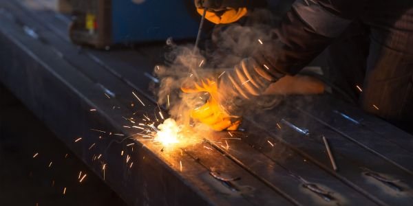
Striking: scratch or tap
- Scratch start. Drag the electrode tip across the plate like striking a match, then lift it immediately to the working arc length. It is the easier method, forgiving on AC and on a cold rod, but the strike mark lands wherever the rod was dragged.
- Tapping start. Bring the electrode straight down, touch the plate and lift at once. It is harder, and a hesitant tap sticks the rod, but it puts the strike exactly where you want it.
- Always strike inside the joint or on the run-on plate, never on the parent metal beside the weld. A stray arc strike is a small quenched, hardened spot and a crack starter, and welding codes treat it as a defect to be removed.
- If the rod sticks, twist it sharply sideways to break it free, and if that fails release the holder at once. A stuck electrode is a short circuit that cooks both the coating and the machine.
Arc length
The standing rule is that the arc length should be about equal to the core wire diameter: roughly 3.2 mm of arc on a 3.2 mm electrode, which puts the arc voltage around 20 to 26 V. Two exceptions are worth knowing.
- Low-hydrogen electrodes want a shorter arc, around half to three-quarters of the core diameter, almost dragging the coating cup on the plate. A long arc on an E7018 lets air into the pool and the low-hydrogen benefit is lost.
- A long arc is the cause of most beginner porosity. The gas shield is only a short column. Stretch the arc and the shield thins out, the arc crackles and wanders, spatter increases and the bead goes wide and flat.
Travel speed
Move so the arc stays on the leading third of the molten pool and the pool stays a constant size behind it. A straight stringer bead should come out about two to three times the electrode diameter wide. Too slow and the bead piles up high, traps slag at its edges and puts excess heat into the plate; too fast and the bead is thin and ropey with poor fusion at the toes. When a wider bead is needed, weave across the joint rather than slowing down, and keep the weave inside about three electrode diameters.
The four welding positions and electrode angles
| Position | Code | Electrode angle | Technique |
|---|---|---|---|
| Flat (downhand) | 1G butt, 1F fillet | Tilted 5 to 15° back from vertical, trailing in the direction of travel. For a fillet, bisect the corner at about 45° to each plate. | The easiest position and the one with the highest deposition rate. Gravity helps the pool. Use the largest sensible electrode and the top of the current range. |
| Horizontal | 2G butt, 2F fillet | 5 to 10° drag angle, plus 5 to 10° tilted upwards so the arc force holds the pool against the upper plate. | The pool wants to sag onto the lower plate. Use stringer beads, a slightly smaller electrode and a shorter arc. Multiple stringers beat one wide weave. |
| Vertical | 3G, 3F | Roughly perpendicular to the plate, tilted about 5 to 10° upwards when welding uphill. | Vertical up gives full penetration and is the structural choice: drop the current 10 to 15%, use a triangular or side-to-side weave, and pause at each edge to fuse the toes. Vertical down is fast and shallow and is used on thin sheet and pipe roots, with electrodes coded for it. |
| Overhead | 4G, 4F | Near perpendicular to the plate with a 5 to 15° drag angle. | The hardest position. Smallest practical electrode, lowest current, shortest arc, stringer beads only, and keep the pool small so surface tension can hold it. Full leathers, because everything that falls, falls on you. |
Slag removal and cleaning between runs
Slag is not waste to be dealt with at the end. Trapped slag is one of the most common defects found on radiographs of stick welds, and it is entirely preventable.
- Let the bead cool a few seconds until the slag darkens and starts to lift or crack by itself. Chipping a glowing bead just smears the slag into the metal.
- Chip from behind the run, pushing the hammer along the weld away from you, so fragments fly forward rather than into your face. Safety glasses stay on under the helmet for this.
- Wire brush every run, including the sides of the groove and the toes of the bead, not just the top.
- Grind out craters at every stop. The crater at the end of a run holds slag and often a small crack. Grind it back to sound metal before restarting there.
- Clean the tack welds too. Slag left on a tack is buried inside the root run and shows up later as an inclusion.
- Inspect between passes. On a multi-run joint, every pass is the surface preparation for the next one. Undercut, overlap or a deep valley between two beads will be sealed in by the following run.
Low-hydrogen electrode storage and re-baking
Basic, low-hydrogen coatings are hygroscopic. Moisture in the coating breaks down in the arc into hydrogen, the hydrogen dissolves in the weld metal, and as the joint cools it collects at the heat-affected zone and causes hydrogen-induced cold cracking, which can appear hours or even days after the weld was made. That is why storage is a procedure and not housekeeping.
- Supply. Low-hydrogen electrodes come in hermetically sealed tins or vacuum packs. Once that seal is broken, the clock starts.
- Holding oven. Keep opened low-hydrogen electrodes in a heated cabinet at 120 to 150 °C (250 to 300 °F), and carry them to the joint in a heated quiver rather than in a pocket.
- Atmospheric exposure. AWS D1.1 allows standard E70XX low-hydrogen electrodes about 4 hours of exposure outside the oven, and up to 9 hours for the moisture-resistant types carrying the R suffix. Higher strength classifications get less.
- Re-baking. Electrodes that have exceeded their exposure time are re-dried at 260 to 430 °C (500 to 800 °F) for at least two hours for the A5.1 carbon steel grades. E8018 and higher strength electrodes are baked at the top of that band, 370 to 430 °C, and are limited to about three one-hour re-dries. Codes normally allow one reconditioning cycle, after which the electrodes are scrapped.
- Never bake cellulosic electrodes. E6010 and E6011 need the few percent of moisture in their coating to make their shielding gas. Put them in an oven and they are ruined. Keep them dry at room temperature and that is all.
- Rutile electrodes such as E6013 only need dry, indoor storage off the floor.
- Warning signs. A damp low-hydrogen rod spits, the coating cracks or flakes off in the arc, and the bead is porous. Discard it rather than arguing with it.
Common stick welding defects, causes and fixes
| Defect | What you see | Cause | Fix |
|---|---|---|---|
| Porosity | Round holes on or under the bead surface | Arc too long, damp electrode, oil, paint, moisture or rust on the joint, draught blowing the gas shield away, wrong polarity | Shorten the arc, use dry electrodes from the oven, clean and dry the joint, screen the work from wind |
| Undercut | A groove melted into the parent metal along the toe of the weld, not filled with metal | Current too high, arc too long, travel too fast, wrong electrode angle, no pause at the edge of a weave | Reduce current, shorten the arc, slow down, hold a moment at each side of the weave |
| Slag inclusion | Dark non-metallic pockets trapped in the weld, usually found on a radiograph | Slag not removed between runs, current too low, bead profile too convex, undercut or a deep valley left for the next pass to bridge | Clean every run completely, raise current a little, grind out pockets and undercut before the next pass |
| Arc blow | The arc bends sideways or backwards, spatter increases, the bead wanders and porosity appears | The magnetic field around a DC welding current is unbalanced, worst near plate ends, corners, heavy fixtures and at high current | Switch to AC, which removes it entirely; otherwise move the earth clamp, use two earth returns, weld towards a heavy tack or towards the clamp, shorten the arc and reduce current |
| Lack of fusion | The weld metal sits on the parent metal without melting into it | Current too low, travel too fast, arc not aimed at the joint face, slag running ahead of the pool | Increase current, slow down, direct the arc into the groove face, keep the arc leading the slag |
| Spatter | Beads of metal stuck around the weld | Current too high, arc too long, damp coating, wrong polarity, arc blow | Correct the setting and the arc length; anti-spatter spray only hides the symptom |
| Cracking | Cracks along the bead, at the crater, or in the heat-affected zone appearing later | Hydrogen from a damp coating, high restraint, fast cooling on thick or hardenable steel, craters left unfilled | Use low-hydrogen electrodes stored correctly, preheat thick or alloy sections, fill every crater, control interpass temperature |
| Poor restart | A lump, a hole or a cluster of pores where a new electrode was started | Restarting on top of an unclean crater | Chip and brush the crater, strike ahead of it, bring the arc back into it, then move forward |
Stick welding versus MIG and TIG
| Factor | Stick (SMAW) | MIG (GMAW) | TIG (GTAW) |
|---|---|---|---|
| Deposition efficiency | Roughly 60%, after stub ends, slag and spatter | Around 90 to 95% | Close to 100% of the filler used |
| Consumable handling | Rods, changed every 300 to 450 mm; low-hydrogen types need an oven | Wire spool, plus a gas cylinder and regulator | Cut filler rods, plus a gas cylinder and tungsten grinding |
| Tolerance of rust, paint and poor fit-up | Good with the right electrode | Poor | Very poor |
| Clean-up after welding | Slag chipped and brushed off every single run | Light spatter only | Almost none |
| Equipment cost and portability | Lowest, and a cable is all you carry to the joint | Medium, plus a wire feeder and cylinder to move | Highest, plus a cylinder and often water cooling |
| Site and repair work | Its natural home: outdoors, at height, in confined spaces | Workshop process | Workshop process |
The TIG welding page sets out the full three-way comparison of arc characteristics, shielding and skill. The practical division of labour is simple enough: stick for site erection, repairs and anything outdoors or dirty; MIG welding for production and sheet work indoors; TIG for root runs, thin stainless and aluminium. On pressure pipework it is common to put the root in with TIG and fill with stick or MIG.
Advantages, limitations and where stick welding is used
Advantages: the cheapest and simplest equipment of any arc process; nothing to carry to the joint but a cable and a rod; no gas cylinders, hoses or regulators; works outdoors and in wind, because the shield is made at the arc; tolerates rust, scale, paint and poor fit-up better than gas-shielded processes; covers carbon steel, low-alloy steel, stainless, cast iron and hardfacing just by changing the electrode; and works in confined spaces, at height and in any position.
Limitations: slow, with a stop every 300 to 450 mm to change electrodes; slag has to be chipped and brushed off every run; deposition efficiency is only about 60% because of stub ends, slag and spatter; not practical much below 2 mm thickness; not used for aluminium, magnesium, titanium or other reactive metals; more spatter and more clean-up than gas-shielded work; fume levels are higher; and low-hydrogen electrodes need oven discipline that small workshops often skip.
Applications: structural steel erection on site, bridges and towers; pipeline and pipe root welding with cellulosic electrodes; shipyard and offshore repair; maintenance and breakdown welding in plants and mines; repair of earth-moving and agricultural machinery; hardfacing of crusher jaws, buckets and tines; cast iron repair with nickel electrodes; and the everyday fabrication of grilles, gates, frames and trusses in workshops all over India, where a single-phase transformer or a small inverter is often the only welding plant on site.
References
- AWS A5.1/A5.1M, Specification for Carbon Steel Electrodes for Shielded Metal Arc Welding, 2025 edition.
- AWS D1.1/D1.1M, Structural Welding Code – Steel, for electrode storage, atmospheric exposure and re-drying requirements.
- Bureau of Indian Standards, IS 814:2004, Covered Electrodes for Manual Metal Arc Welding of Carbon and Carbon Manganese Steel – Specification.
- IEC 60974-1, Arc welding equipment – Welding power sources, for the ten-minute duty cycle basis.
- American Welding Society, arc welding process definitions and classifications.
FAQs
What is stick welding and how does it work?
Stick welding, formally shielded metal arc welding (SMAW), joins metal by striking an electric arc between a flux-coated consumable electrode and the workpiece. The arc melts both the electrode core and the parent metal into a common pool, while the coating burns to release a shielding gas and forms a slag layer over the cooling bead. The electrode supplies the filler metal and is consumed, so it is replaced every 300 to 450 mm of welding.
What does the number on a welding electrode mean?
In the AWS A5.1 system for carbon steel, E7018 reads as follows: E is a covered electrode, 70 is the minimum tensile strength of the deposit in thousands of psi (70,000 psi, about 483 MPa), 1 means it can be used in all positions, and the last digit read with the position digit gives the coating type and current, here a low-hydrogen iron-powder coating run on DCEP or AC. Indian electrodes follow IS 814, which codes covering type, strength, elongation and impact, position, current and open circuit voltage in that order.
Which polarity is used for stick welding?
DCEP, electrode positive, is the usual choice because it gives the deepest penetration and the most stable arc, and it is what E6010 and E7018 are designed for. DCEN, electrode negative, melts the electrode faster with shallower penetration and suits thin sheet. AC is used with electrodes such as E6011 and E6013, and is the standard cure for magnetic arc blow. Note that this is the opposite of the TIG rule, where electrode negative gives the deeper penetration.
What current should I set for a 3.2 mm electrode?
Around 90 to 140 A for a 3.2 mm electrode on plate in the flat position, following the rough guide of 30 to 45 A per millimetre of electrode diameter. Drop 10 to 15% for vertical and overhead work. Then read the bead: a stuttering arc, a high narrow bead and slag that will not release mean the current is too low, while a roaring arc, heavy spatter, a red-hot electrode and undercut at the toes mean it is too high.
Why do 7018 electrodes have to be kept in an oven?
Because their basic coating absorbs moisture from the air, and that moisture becomes hydrogen in the arc. Dissolved hydrogen causes cold cracking in the heat-affected zone, sometimes days after welding. Opened low-hydrogen electrodes are held at 120 to 150 °C, allowed roughly four hours of atmospheric exposure (about nine hours for moisture-resistant R grades), and re-baked at 260 to 430 °C for at least two hours if that is exceeded. Cellulosic electrodes such as E6010 are the opposite case and must never be baked, since they need the moisture in their coating.