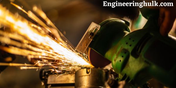
A grinding machine finishes a part by cutting it with thousands of hard abrasive grains bonded into a fast-spinning wheel, and the main types are surface, cylindrical, centreless, internal, tool and cutter, jig, gear and CNC grinding machines. Each type is defined by how it holds the work and which surface the wheel can reach. Precision grinding routinely holds tolerances of about ±0.005 mm with a surface finish of 0.2 to 0.8 micron Ra, and fine wheels with spark-out passes reach 0.1 micron Ra or better.
What grinding is and why it is used
In grinding, the cutting edges are abrasive grains rather than ground teeth on a solid tool. Each grain takes a chip only a few microns thick, and so many are in contact that the wheel behaves like a cutter with thousands of tiny, randomly placed, heavily negative-rake teeth. Three reasons keep it in the process plan even though it removes metal slowly:
- Surface finish. Turning typically leaves 1.6 to 6.3 micron Ra; cylindrical grinding gives 0.2 to 0.8 micron Ra. Bearing journals, seal faces and hydraulic bores need that finish or they leak and wear.
- Hardness. A hardened steel workpiece at 58 to 62 HRC destroys a carbide insert but grinds normally. Grinding is usually the only economic way to finish a part after heat treatment, which matters because heat treatment distorts parts.
- Close tolerance. Grinding works at IT5 and IT6 levels of accuracy. Typical shop capability is ±0.005 mm, precision work ±0.002 mm, and machines with in-process gauging hold ±0.001 mm on diameter.
The trade-off is heat. Almost all the energy goes into a very small contact zone, so coolant supply, wheel choice and dressing decide whether you get a good part or a burned one.
Abrasive wheel basics: the five things in a wheel code
The wrong wheel on the right machine still gives a bad part. A bonded wheel is described by five characteristics: abrasive, grit, grade, structure and bond.
| Abrasive | Symbol | Best on | Note |
|---|---|---|---|
| Aluminium oxide | A (WA white) | Carbon and alloy steel, HSS, wrought iron, tough high tensile materials | The general-purpose abrasive. White grit is friable and runs cooler on hardened tool steel. |
| Silicon carbide | C (GC green) | Cast iron, brass, bronze, aluminium, rubber, stone, cemented carbide | Harder but more brittle. Suits low tensile and non-ferrous materials; green grit sharpens carbide tools. |
| Cubic boron nitride | B (CBN) | Hardened steels above about 50 HRC, tool and die steel, hardened gears and cams | Next to diamond in hardness and chemically stable against iron. Long life, low thermal damage, high cost. |
| Diamond | D, SD | Tungsten carbide, ceramics, glass, concrete, composites | Hardest abrasive. Avoid on plain steel at high temperature, because carbon diffuses into the iron and the grains wear away. |
- Grit (grain size) is a mesh number: roughly 8 to 24 coarse, 30 to 60 medium, 70 to 180 fine, 220 and above very fine. Coarse removes stock fast, fine gives finish and holds form.
- Grade is how strongly the bond holds the grains, not the hardness of the grains. It runs A (soft) to Z (hard). Rule of thumb: soft grade on hard material, hard grade on soft material, softer grade as the contact area grows.
- Structure is grain spacing, numbered about 1 (dense) to 15 (open). Open structure gives chip clearance and coolant access on soft, gummy metals and wide contacts.
- Bond is V vitrified (glass, about three-quarters of all wheels), B resinoid (tough, for high speed and cut-off), R rubber, S silicate, E shellac and M metal for diamond and CBN.
Worked example: decoding the marking A46K5V
Indian Standard IS 551 sets the coding system for bonded abrasive products, and it reads left to right in that order. For a wheel marked A46K5V:
- A = aluminium oxide, so it is a wheel for steel.
- 46 = grit size 46, medium grain, general purpose stock removal with a fair finish.
- K = medium grade, soft enough that dull grains break away and expose fresh edges on hardened steel.
- 5 = structure 5, medium spacing.
- V = vitrified bond.
A full specification adds a manufacturer’s prefix for the abrasive variant and a suffix for the exact bond, so the same wheel may appear as 51A46K5V23. Compare GC60J8V: green silicon carbide, grit 60, softer grade J, open structure 8, vitrified, which is a carbide tool grinding wheel.
Types of grinding machines and their uses
This table is the short answer; the detail follows. The tolerances are typical for a well-maintained production machine, not the limit of the best machines.
| Machine type | What it grinds | Typical tolerance | Application |
|---|---|---|---|
| Surface grinder | Flat work on a magnetic chuck | ±0.005 mm flatness and parallelism; 0.2 to 0.8 micron Ra | Die plates, fixture bases, gauge blocks, machine slides, mould parting lines |
| Cylindrical grinder (plain) | Outside diameters between centres or in a chuck | ±0.005 mm on diameter; roundness 0.002 to 0.005 mm | Shafts, spindles, pins, rolls, bearing journals |
| Universal cylindrical grinder | Same, plus swivelling head and table for tapers and bores | ±0.005 mm; angles to a few minutes of arc | Tool room work, tapers and short bores in one setup |
| Centreless grinder | Unclamped round bar on a blade between two wheels | ±0.002 to ±0.005 mm on diameter; roundness to 0.001 mm | High volume pins, dowels, needle rollers, valve stems, injector parts |
| Internal grinder | Bores, with a small quill-mounted wheel | ±0.005 mm on bore; 0.4 to 0.8 micron Ra | Bearing races, gear bores, cylinder liners, hydraulic valve bodies |
| Tool and cutter grinder | Cutting tools, on a universal head with tooth rests | Angles within a few minutes of arc; concentricity 0.005 mm | Resharpening milling cutters, reamers, drills, hobs, form tools |
| Jig grinder | Hole size and position in hardened plate | Position within 0.002 to 0.005 mm | Press tool dies, punches, moulds and gauges after heat treatment |
| Gear grinder | Tooth flanks of hardened gears | DIN quality class 3 to 5; 0.2 to 0.6 micron Ra on the flank | Automotive transmission gears, aerospace and wind turbine gearing |
| CNC grinder | Any of the above, under program control | ±0.001 to ±0.005 mm, repeatable part to part | Volume production, complex forms, multi-operation setups |
Surface grinding machine
The work sits on a magnetic chuck and the wheel skims the top face. Four layouts exist, named by spindle orientation and table motion:
- Horizontal spindle, reciprocating table. The common tool room machine. The wheel periphery cuts, the table strokes under it, the wheel steps across at each end. Cuts of 0.005 to 0.02 mm and excellent finish.
- Horizontal spindle, rotary table. Round parts spin under a peripheral wheel. Faster than reciprocating for discs and rings.
- Vertical spindle, reciprocating table. A cup or segmental wheel cuts on its face, so contact area and stock removal are high but the finish shows a cross-hatch pattern.
- Vertical spindle, rotary table. A production layout: parts load around a rotating chuck and pass continuously under a large cup wheel. Clutch plates, brake discs, valve plates.
Creep-feed grinding is a variant of the reciprocating machine: instead of many 0.02 mm passes it takes one or two passes 1 to 6 mm deep at very slow table speed, with heavy coolant and a soft open wheel, grinding a form straight from solid. It is standard for turbine blade fir-tree roots.
Cylindrical grinding machine
The work turns between centres or in a chuck while the wheel grinds the outside diameter. The plain machine does straight diameters and shoulders, with the table swivelling a few degrees for shallow tapers. The universal machine adds a swivelling workhead, a swivelling wheelhead and an internal attachment, so steep tapers and a bore can be done without re-chucking; it is less rigid, which is why production shops still prefer the plain machine.
Traverse grinding moves the work past a narrow wheel and suits long shafts. Plunge grinding uses a wheel wider than the ground length and feeds straight in, which is faster and can grind a shoulder and diameter together, but needs more power and better coolant.
Centreless grinding machine
Centreless grinding is the throughput champion, and the reason is that the part is never clamped. It rests on a hardened work-rest blade between a large grinding wheel and a smaller regulating wheel. No centres, no chucking, no loading time per part.
The regulating wheel is what students usually misunderstand. It is a rubber or resin bonded wheel run slowly, typically 15 to 60 rpm, and its job is friction, not cutting: it drives the part at roughly its own surface speed while the grinding wheel, running far faster, does the cutting. The work centre is set above the line joining the two wheel centres, usually by about half the work diameter, and that offset is what rounds the part up instead of grinding a lobed shape of constant diameter.
- Through-feed. The regulating wheel is tilted by a small angle, commonly 1 to 5 degrees, so it pulls the bar along as it spins it. Parts go in one end and out the other continuously. Axial feed = pi x D x N x sin(alpha). For a 250 mm regulating wheel at 30 rpm tilted 3 degrees: pi x 0.25 x 30 x sin 3 = 1.23 m/min. Straight plain parts only, no shoulders.
- In-feed. The tilt is removed and an end stop locates the part. The regulating wheel feeds in radially, grinds a shouldered or formed part and retracts. The centreless equivalent of plunge grinding.
- End-feed. The part is fed axially against a fixed stop and ground by a taper formed on the wheels, for short taper shanks and conical parts.
The catch is setup time, and the fact that centreless grinding controls size and roundness only. It cannot control the position of the ground diameter relative to any other feature.
Internal grinding machine
Bores are ground with a wheel much smaller than the hole, on a slender quill. Because the wheel is small it must spin very fast, often 20,000 to 60,000 rpm, just to reach a usable surface speed, and the quill deflects, so cuts are light and spark-out passes are needed. Types are chucking (work rotates), planetary (work stationary, wheel orbits the bore, for large castings) and centreless internal, used on bearing races where the bore must be concentric with a finished outside diameter.
Tool and cutter grinder
A universal machine for sharpening cutting tools. It has a swivelling wheelhead, a table that swivels in plan, a universal workhead and a tooth rest that indexes the cutter one tooth at a time so every flute gets the same relief angle. Typical jobs are relief grinding on milling cutters, end mill flutes, reamer chamfers and drill point angles.
Jig grinder
A jig grinder is a jig borer that grinds. The spindle spins at high speed and also orbits in a planetary path whose radius is set in microns, so it can bring a hole to exact size and position in a plate that has already been hardened, to 0.002 to 0.005 mm. Die makers use it to correct heat-treatment distortion, which no other process can do at this accuracy.
Gear grinding machine
Hardened gear teeth are ground to remove distortion and correct the profile. In form grinding a dressed wheel matching the tooth space grinds one gap and then indexes. In generating or threaded-wheel grinding a worm-shaped wheel runs like a hob in timed rotation with the gear and finishes all teeth continuously. Generating is far faster and is standard in automotive gearboxes; form grinding suits large, low-volume and internal gears.
Types of CNC grinding machines
CNC grinding machines are the same families listed above with servo-driven axes, a programmable wheel head, automatic dressing with size compensation, and gauging that feeds the measured size back into the cycle. The gain is not only accuracy; it is that the hundredth part matches the first.
- CNC cylindrical grinder. Often a B-axis wheelhead carrying two or three wheels, so a diameter, a shoulder and a taper are ground in one chucking. Angular-head versions grind a face and a diameter in one plunge.
- CNC surface and profile grinder. Continuous-path control plus a dressing unit that generates a form on the wheel, so a whole profile is ground from solid. This is where creep-feed grinding lives.
- CNC centreless grinder. Regulating wheel speed, tilt and in-feed are programmed and both wheels dress automatically, cutting changeover between part numbers from hours to minutes.
- CNC internal grinder. Multi-spindle turrets swap between a bore wheel and a face wheel without unloading, keeping bore and face square to each other.
- CNC tool and cutter grinder. Five axes, wheel-pack changers and 3D simulation software. The dominant machine for making solid carbide drills and end mills from blank bar.
- CNC jig grinder. Programmed planetary motion and automatic wheel changing for die and mould work.
- CNC gear grinder. Electronic gear train instead of change gears, with automatic stock dividing and profile modification such as crowning and tip relief.
- CNC double-disc grinder. Grinds two parallel faces at once between opposed wheels, for connecting rods, pump vanes and saw blades.
A note for students: CNC does not change the physics. Wheel selection, dressing condition and coolant still decide the outcome, and the machine simply repeats your decision, good or bad, a thousand times.
Wheel dressing and truing
The two words are often used interchangeably, and they should not be. Truing makes the wheel concentric with its spindle and gives it the shape you want; a new wheel is trued after mounting because no wheel runs true out of the box. Dressing restores the cutting surface, breaking away dulled grains and clearing loaded metal to expose fresh edges. A wheel needs dressing many times before it needs truing again.
The tools are the single-point diamond dresser (the tool room standard), the diamond roll (a formed roll that re-creates a profile in seconds, used on CNC production machines) and the star dresser for coarse offhand work. Dressing depth is typically 0.01 to 0.03 mm per pass, and the lead, meaning how fast the dresser crosses the face, sets the result: a fast lead leaves an open free-cutting wheel, a slow lead a closed wheel that finishes better but runs hotter.
Grinding defects, causes and fixes
| Defect | What you see | Cause | Fix |
|---|---|---|---|
| Burning | Blue or brown discolouration, sometimes cracks and a soft rehardened skin | Too much heat in the contact zone: wheel too hard, dressing too fine, depth of cut too high, coolant not reaching the contact | Softer or more open wheel, dress coarser, reduce infeed, raise work speed, aim the coolant nozzle into the wheel-work gap at wheel speed |
| Chatter | Regular or wavy marks on the surface, audible ringing | Out-of-balance wheel, worn spindle bearings, loose work support, wheel too hard, machine resonance | Balance and true the wheel, check bearings and centres, add a steady rest, change wheel speed to move off the resonant frequency |
| Glazing | Shiny wheel face, rising power draw, part heats and stops sizing | Grade too hard for the job or wheel speed too high, so dull grains will not release | Dress the wheel, move to a softer grade, reduce wheel speed or increase work speed |
| Loading | Metal smeared into the wheel pores, poor finish, burning | Soft or gummy material such as aluminium, copper or mild steel; structure too dense; insufficient coolant | Open structure and coarser grit, dress to clear the pores, more coolant, lighter cuts |
| Taper or out-of-round | Diameter varies along or around the part | Table swivel off, centres worn or dry, not enough spark-out, work deflecting | Set the table with a test bar, regrind and lubricate the centres, add spark-out passes, support the work |
Grinding wheel safety
A wheel that bursts at operating speed is one of the most dangerous events in a workshop, so these rules are not optional.
- Ring test every vitrified wheel before mounting. Hang it on a pin and tap lightly with a non-metallic handle about 45 degrees either side of the vertical centreline, on both faces. A sound wheel gives a clear metallic ring, a cracked one a dull thud. The wheel must be clean and dry or the sound is deadened.
- Never exceed the maximum operating speed printed on the wheel and its blotter. Check that spindle speed times wheel circumference stays below it, and re-check after fitting a larger wheel.
- Use blotters between the wheel and matching flanges of at least one-third the wheel diameter, and tighten the nut only enough to hold the wheel, since over-tightening cracks it.
- Keep the guard on. On a pedestal grinder set the work rest within 3 mm of the wheel and the tongue guard within 6 mm, adjusting both only with the wheel stopped.
- Run a new wheel for at least a minute with everyone clear of the plane of rotation before touching work to it.
- Wear a face shield over safety glasses, store wheels in a dry rack, and scrap any wheel that has been dropped or soaked in coolant rather than testing and using it.
Housekeeping matters after the cut too: sensible methods to prevent corrosion keep a freshly ground surface precise until it reaches assembly.
References
- Bureau of Indian Standards, IS 551, bonded abrasive products, which defines the marking and coding system used above.
- AICTE Model Curriculum – Manufacturing Technology, for the syllabus coverage of grinding in Indian diploma and B.Tech programmes.
FAQs
What are the main types of grinding machines?
Surface grinders (horizontal or vertical spindle, with reciprocating or rotary tables), cylindrical grinders (plain, universal and internal), centreless grinders (through-feed, in-feed and end-feed), tool and cutter grinders, jig grinders, gear grinders and CNC grinding machines. They differ in how the work is held and which surface the wheel can reach.
What are the types of CNC grinding machines?
The main CNC families are cylindrical (often with a B-axis multi-wheel head), surface and profile, centreless, internal, 5-axis tool and cutter, jig and gear grinders, plus double-disc machines. All add programmed axes, automatic dressing with size compensation and in-process gauging, so every part in a batch repeats to the same size.
What does the grinding wheel marking A46K5V mean?
A is aluminium oxide abrasive, suited to steels. 46 is the grit size, a medium grain. K is the grade, meaning medium bond strength. 5 is the structure, medium grain spacing. V is a vitrified bond. Read together it is a general-purpose medium wheel for grinding steel.
What tolerance and surface finish can a grinding machine hold?
Typical production grinding holds about ±0.005 mm on size with 0.2 to 0.8 micron Ra. Precision machines reach ±0.002 mm, and with in-process gauging, fine wheels and spark-out passes, ±0.001 mm and finishes below 0.1 micron Ra are achievable on cylindrical and centreless work.
What is the difference between dressing and truing a grinding wheel?
Truing shapes the wheel and makes it run concentric with the spindle. Dressing sharpens the cutting face by breaking off dull grains and clearing loaded metal. A wheel needs dressing often during a shift, but truing only when it is newly mounted or its form has been lost.