 EngineeringHulk
- Home
- Blog
- Electrical & Electronics
- Honeywell XNX Universal Transmitter: Basics, Uses and Applications
Honeywell XNX Universal Transmitter: Basics, Uses and Applications
On this page
- What is the Honeywell XNX transmitter?
- The personality card: how one transmitter suits three sensor families
- Inputs and outputs: 4-20 mA, HART, Modbus, Fieldbus and relays
- Certification and area classification
- Display, LEDs and the menu
- Calibration and bump testing in practice
- Typical installations and applications
- References
- FAQs
- Related Topics on EngineeringHulk
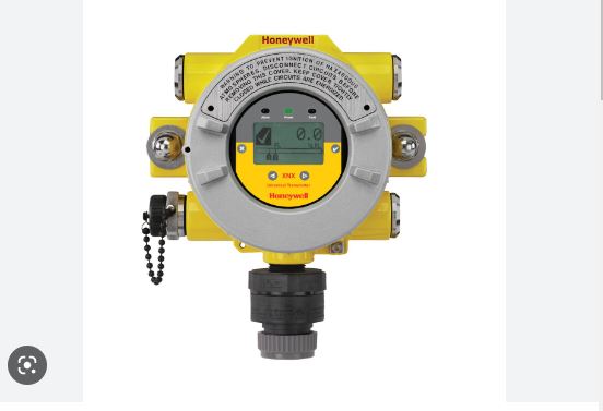
The Honeywell XNX Universal Transmitter is a fixed-point gas detection transmitter that accepts any of Honeywell’s industrial gas sensor technologies on one flameproof platform and converts the sensor signal into a 4-20 mA, HART, Modbus, Foundation Fieldbus or relay output. It is called universal because one enclosure and one user interface can serve an electrochemical toxic sensor, a catalytic bead flammable sensor, a point infrared sensor or an open-path infrared beam, depending on which personality board is fitted inside. The unit is certified for Zone 1 and Zone 2, Zone 21 and 22, and North American Class I and Class II Division 1 and 2 areas.
Everything below comes from Honeywell’s own XNX datasheet and Quick Start Guide. For any real installation, commissioning or calibration job, the XNX Technical Manual supplied with the unit governs, not an article, and defaults differ between order codes.
What is the Honeywell XNX transmitter?
A gas detector has two halves: the sensor that reacts to gas, and the transmitter that powers the sensor, interprets its raw signal, shows a reading and sends a standard output to a fire and gas panel or DCS. The XNX is the second half.
The body is a flameproof (Ex d) enclosure in either five-coat marine-finish painted aluminium alloy or 316 stainless steel, with two integral mounting lugs and five cable or conduit entries: M25 on the ATEX/IECEx version, 3/4 inch NPT on the UL/CSA version. The bottom entry usually carries the sensor itself; the rest take field wiring or blanking plugs.
Inside, the electronics sit in a plug-in module Honeywell calls the POD, short for Personality, Options and Display. Pulling the POD out gives access to the terminal area. The POD carries the LCD, the magnetic switches, the personality board that matches the sensor type, and any optional output board.
| Item | Specification |
|---|---|
| Housing material | Painted marine-grade aluminium alloy, or 316 stainless steel |
| Dimensions | 160 mm x 197 mm x 114 mm |
| Weight | 2.8 kg (aluminium), 5 kg (316 stainless) |
| Entries | 5 off, M25 (ATEX/IECEx) or 3/4 inch NPT (UL/CSA) |
| Ingress protection | IP66 to EN 60529, NEMA 4X |
| Operating temperature | -40 °C to +65 °C (sensor may be narrower) |
| Operating humidity | 0-99% RH, non-condensing |
| Supply voltage | 16-32 V DC (EC and mV), 18-32 V DC (IR), 24 V DC nominal |
| Power consumption (max) | EC 6.2 W, mV 6.5 W, IR with Optima Plus 9.7 W, IR with Excel receiver 13.2 W |
| Field terminals | Pluggable cage type, 0.5 mm² to 2.5 mm² conductors |
The personality card: how one transmitter suits three sensor families
The personality board is the piece that makes the XNX universal. It is the interface circuit between the sensor and the main board, and it is chosen at order time by a letter in the part number, not by a software setting. Three personalities exist.
| Personality | Signal it handles | Sensors supported | Typical measurement |
|---|---|---|---|
| mV | Millivolt bridge output | MPD catalytic bead, MPD infrared (hydrocarbon, methane, CO2), Sensepoint HT, Sensepoint PPM, Model 705 HT | Flammable gas 0-100% LEL; CO2 or methane by volume on the IR cartridges |
| EC | Electrochemical cell current, through an intrinsically safe barrier | XNX EC toxic and oxygen cartridges (H2S, CO, SO2, NH3, Cl2, NO2, H2, HCN, O3, ethylene oxide and others) | Toxic gas in ppm; oxygen in % volume |
| IR | Digital link to a separately powered infrared detector | Searchpoint Optima Plus point IR, Searchline Excel open-path IR, generic 4-20 mA inputs | Point or open-path flammable gas; Excel covers open paths from 5 m to 40 m |
The value shows up on a plant with mixed hazards. A refinery may need catalytic bead detection at a pump seal, an H2S cell near a sour-gas line and an open-path beam across a tank farm bund. With XNX all three report through the same enclosure type, the same display, the same menu tree and the same spare POD in the store, so technicians learn one interface instead of three.
The EC sensor interface is intrinsically safe, which lets an EC cartridge be hot-swapped in a live hazardous area without a hot work permit. Catalytic and IR cartridges in the MPD housing are field-serviceable as well.
Inputs and outputs: 4-20 mA, HART, Modbus, Fieldbus and relays
Every XNX ships with an isolated 4-20 mA output carrying HART 6.0 digital communication on top of it. Optional boards add one of three other output types, and here is the catch that surprises people on their first order: relay, Modbus and Foundation Fieldbus are mutually exclusive. You can have only one of the three fitted in a given transmitter.
- 4-20 mA (standard). Selectable as current source, current sink or fully isolated, set by switches on the back of the POD, so the same unit suits most control-system wiring topologies. Signal accuracy is ±1% of full scale.
- HART (standard). Gives reading, gas name and units, mA level, sensor diagnostics, optical signal level, raw reading, supply voltage, temperature, fault and alarm history, and zero calibration from a handheld or the control room. An optional intrinsically safe local HART port can be fitted into one of the cable entries so a HART 275/375 handheld can be connected without opening the enclosure.
- Relay option. Three user-configurable relays: two SPCO alarm relays and one SPCO fault relay, rated by the datasheet at a maximum of 240 V AC, 5 A non-inductive and a minimum of 5 V, 10 mA. Alarm relays ship normally de-energised.
- Modbus RTU option. Isolated RS485, 1200 to 19,200 baud, multi-drop, up to 254 XNX transmitters on one network.
- Foundation Fieldbus option. H1 physical layer at 31.25 kbit/s to IEC 1158-2 and ISA 50.02, up to 32 nodes.
The current loop also carries status, not just concentration. As shipped, the XNX drives 2.0 mA for inhibit, 3.0 mA for a warning and 21.0 mA for over-range, with fault below 1 mA. Those levels are adjustable within defined bands: 1 to 4 mA for inhibit, warning, beam blocked and low signal, and 20 to 22 mA for over-range. Whoever configures the panel must use the same numbers, otherwise a maintenance inhibit reads as a live fault in the control room.
Cable size decides how far the transmitter can sit from its supply. For an XNX mV with an MPD catalytic sensor on a single-transmitter run, Honeywell quotes about 551 m on 1.5 mm² and 1408 m on 2.5 mm². Screen the cable and earth the screen at one end only, at the detector or the controller, never both.
Certification and area classification
The XNX is built for classified areas, and the certification marking on the label is what an inspector will check against the area classification drawing.
- ATEX: II 2 (1) G Ex d [ia IIC Ga] IIC T4/T6 Gb, and II 2 (1) D Ex tb [ia IIIC Da] IIIC T85 Db for dust.
- IECEx: Ex d [ia IIC Ga] IIC T4/T6 Gb, Ex tb [ia IIIC Da] IIIC T85 Db.
- UL: Class I Division 1 Groups A, B, C and D; Class II Division 1 Groups F and G; Class I Zone 1 Groups IIB + H2.
- CSA: Class I Division 1 Groups B, C and D; Class II Division 1 Groups F and G.
- Functional safety: assessed to IEC 61508 and suitable for use up to SIL 2.
- Performance approvals: EN 60079-29-1, EN 50104, EN 50271, EN 45544 in Europe; UL 913, UL 1203 and CSA 22.2 No. 152 in North America.
Read the marking in pieces. Ex d is the flameproof enclosure: an internal ignition is contained and cooled by the flame paths, which is why cover threads and flame paths must never be damaged, painted over or left partly engaged. [ia IIC Ga] is the intrinsically safe circuit going out to the sensor, and T4/T6 is the surface temperature class. For Indian projects the route is a PESO/CCoE approval based on the IECEx or ATEX certificate, with installation to IS/IEC 60079-14, so confirm the certificate held for the specific model before designing it into a plant.
Display, LEDs and the menu
The front face carries a backlit multilingual LCD and three LEDs: green for power, red for alarm, yellow for fault. The LEDs code the condition by state, so a solid red is Alarm 1, a flashing red is Alarm 2, a solid yellow is a warning, a flashing yellow is a fault and a flashing green is the health signal. The screen shows concentration as digits and as a bar graph against full scale, with the units and a status icon.
Configuration is non-intrusive: four magnetic switches sit behind the glass and the operator swipes the supplied magnetic wand over the shaded areas to work them, so routine menu work needs no enclosure opening and no hot work permit. The switches are enter/accept, escape/back, left/decrement and right/increment. Swiping escape from the status screen brings up the alarm reset screen; swiping enter brings up the passcode screen. Two access levels exist, Level 1 for routine maintenance and Level 2 for technician and password administration, and both leave the factory set to 0000, so both should be changed at commissioning. Past the passcode sits the main menu, where Gas Calibration holds zero and span calibration, bump test, mA output calibration, soft reset and, for an open-path unit, Align Excel.
Other defaults worth knowing: alarms ship latching and faults non-latching, the calibration reminder is set to 180 days, and HART starts at address 0 in point-to-point mode while Modbus starts at address 5 and 19,200 baud.
Calibration and bump testing in practice
A gas detector that is never gas-tested is a decoration. Two different jobs keep it honest, and they are not interchangeable.
A bump test (functional gas test) applies a known test gas briefly and checks that the detector responds and the alarms act. It does not adjust anything. On the XNX it has its own menu entry, and the screen shows the live reading alongside the peak reading reached during the test. If the peak is outside the limits your site accepts, you move on to a calibration; if calibration does not fix it, the sensor is replaced. Honeywell’s guidance is to bump test frequently, with the interval decided by the gas, the environment and the site’s own procedure.
A calibration sets the two ends of the scale: a zero in clean air or bottled 20.9% volume oxygen, then a span with certified test gas. Honeywell recommends a maximum calibration interval of 30 days, or whatever the site procedure states. Points that come straight from the guide:
- Let a newly powered detector stabilise for 30 minutes before the first calibration, and use a flow regulator set to 300-375 mL/min with the calibration flow housing that clips to the sensor.
- During zero and span the current output is inhibited (3 mA by default on EC and MPD calibration) so the panel does not see a false alarm. Inhibit also silences alarms, so a genuine release would go unreported and inhibit must be cleared the moment the work ends.
- Zero an H2S cell with bottled 20.9% volume oxygen rather than background air, and apply the span gas immediately afterwards without letting the cell return to ambient air.
- An oxygen cell needs no zeroing; background air at 20.9% volume can be used to span it.
- Recalibrate if ambient temperature has moved more than about ±15 °C from the temperature of the last calibration. Default calibration point for flammable sensors is 50% LEL.
Cell life is finite. With three-monthly visual inspection and six-monthly test and recalibration, Honeywell gives an expected life of at least 24 months for oxygen and most toxic cells, 18 months for chlorine and chlorine dioxide, and 12 months for ammonia and hydrogen fluoride.
Typical installations and applications
XNX transmitters are used where a flammable or toxic release is credible and the area is classified: offshore platforms, drilling rigs, refineries, chemical and petrochemical plants, onshore oil and gas terminals, gas transmission stations and power plants. In Indian practice the same units turn up in LPG bottling plants, fertiliser and ammonia handling areas, effluent and sewage pump houses where H2S collects, and battery rooms where hydrogen can accumulate.
Mounting options cover surface, pipe, ceiling and duct with the matching kits. The sensor need not sit on the transmitter: an EC sensor can be mounted up to 15 m away on its intrinsically safe remote kit, and the IR personality drives a Searchpoint Optima Plus or Searchline Excel placed where the gas is expected.
Placement decides whether the system works at all. Detectors for gases heavier than air, such as propane, butane or chlorine, go low; hydrogen, ammonia and methane rise, so those go high. Put them near credible leak sources (flanges, pump seals, compressor skids, sample points) and in the ventilation path, and keep the display and calibration port reachable for the technician who has to gas-test the unit every month.
References
- Honeywell, XNX Universal Transmitter product page.
- Honeywell Analytics, XNX Universal Transmitter Quick Start Guide (1998M0813) and XNX Universal Transmitter Technical Manual (1998M0738).
- Honeywell Analytics, XNX Universal Transmitter datasheet, technical summary and ordering information.
FAQs
What is the Honeywell XNX transmitter used for?
It is a fixed gas detection transmitter for hazardous industrial areas. It powers a Honeywell gas sensor, displays the reading, and sends 4-20 mA with HART, plus optional Modbus, Foundation Fieldbus or relay outputs to a fire and gas panel. It covers flammable gas, toxic gas and oxygen depletion.
What does the personality board in an XNX do?
It is the interface card that matches the transmitter to one family of sensors. The mV board takes millivolt sensors such as the MPD catalytic bead and Sensepoint, the EC board takes electrochemical toxic and oxygen cartridges, and the IR board drives Searchpoint Optima Plus and Searchline Excel infrared detectors. The personality is set by the order code.
Can an XNX have relays and Modbus at the same time?
No. The relay board, the Modbus RTU board and the Foundation Fieldbus board are mutually exclusive, so only one option board can be fitted. The 4-20 mA output with HART is standard on every unit regardless of which option is chosen.
How often should an XNX gas detector be calibrated?
Honeywell recommends a maximum calibration interval of 30 days, or the interval set by the site procedure, with frequent bump tests in between. The shipped calibration reminder is set to 180 days, so it is usually changed at commissioning to match the site rule.
Which hazardous areas is the XNX approved for?
Zone 1 and Zone 2 for gas, Zone 21 and Zone 22 for dust, and North American Class I and Class II Division 1 and 2. It carries ATEX, IECEx, UL and CSA approvals with an Ex d flameproof enclosure and an intrinsically safe sensor circuit, and it is assessed to IEC 61508 for use up to SIL 2.
Related Topics on EngineeringHulk
Keep reading
Applications of Zener Diode: Uses, Worked Regulator Design, Advantages and Disadvantages
Applications of Zener diode: voltage regulator (worked design), reference, clipper, surge and meter protection, with ratings, advantages and disadvantages.
Stroboscope: Working Principle, RPM Measurement, Types and Uses
How does a stroboscope work? Flashes at the rotation rate freeze motion. Working principle, RPM method, the harmonic trap, worked example, types, uses.

Kirchhoff’s Laws: KCL and KVL Statement, Applications and Solved Example
KCL statement: currents at a junction sum to zero. KVL statement: voltages round a loop sum to zero. Both laws with a solved two-loop circuit.
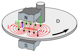
Eddy Current: Working Principle, Loss Formula, Advantages and Applications
Eddy currents are looping currents induced in a conductor by a changing magnetic field. Working principle, loss formula, laminations and applications.
DOL Starter (Direct-On-Line Motor Starter): Working, Parts and Uses
A DOL (direct-on-line) starter connects an induction motor to full voltage in one step. Parts, working, starting current, DOL vs star-delta, pros and cons.
Who Invented Electricity? A Timeline of the People Who Discovered It
Nobody invented electricity: it is a natural force discovered step by step. See who did what, from Thales and Gilbert to Volta, Faraday, Edison and Tesla.