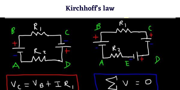
Kirchhoff’s current law (KCL) states that the algebraic sum of currents at any junction of a circuit is zero, and Kirchhoff’s voltage law (KVL) states that the algebraic sum of potential differences around any closed loop is zero. KCL follows from conservation of charge, KVL from conservation of energy. Written as formulas: ΣI = 0 at a node, ΣV = 0 around a loop. Together they solve any circuit that resistors in series and parallel cannot reduce, such as a two-battery network or an unbalanced Wheatstone bridge.
Gustav Kirchhoff published both rules in 1845, while still a student at Königsberg. They remain the working tools of every circuit analysis method used today, including mesh and nodal analysis.
KCL statement: Kirchhoff’s current law
At any junction (node) in an electric circuit, the algebraic sum of the currents is zero. Equivalently, the total current flowing into a junction equals the total current flowing out of it.
In symbols:
ΣI = 0, or ΣIin = ΣIout
Why KCL is true
Charge is conserved and a junction is just a point of wire. It cannot store charge, create it or destroy it. Whatever arrives per second has to leave per second, otherwise charge would pile up at the node and its potential would climb without limit, which does not happen in a steady circuit.
KCL sign convention
Fix one sense before you write the equation and keep it for the whole problem:
- Currents flowing into the node are positive.
- Currents flowing out of the node are negative.
If currents of 5 A and 3 A enter a node and one current I leaves it, the equation is 5 + 3 − I = 0, so I = 8 A. The direction you assume for an unknown current does not have to be correct. If you guess wrong, the algebra returns a negative value and that minus sign is the answer telling you the real current runs the other way.
KCL in a circuit with n nodes
A circuit with n nodes gives n − 1 independent KCL equations. The last node’s equation is the sum of all the others, so it adds nothing new. Pick any node as the reference (ground) and write KCL at the remaining ones.
KVL statement: Kirchhoff’s voltage law
Around any closed loop in a circuit, the algebraic sum of all potential differences is zero. Equivalently, the sum of the EMFs in a loop equals the sum of the IR drops in that loop.
In symbols:
ΣV = 0, or Σε = ΣIR
Why KVL is true
Electric potential is a single-valued property of a point in a steady circuit. Walk around a loop and come back to where you started, and you must be at the same potential you left. The energy given to a coulomb of charge by the sources is exactly the energy it gives up in the resistances. KVL is conservation of energy written per unit charge.
KVL sign convention
Choose a direction to walk the loop, clockwise or anticlockwise, then apply these rules at every element:
| Element | Direction of travel | Sign of the term |
|---|---|---|
| Resistor R carrying current I | Same direction as the current | −IR (a drop) |
| Resistor R carrying current I | Against the current | +IR (a rise) |
| Cell of EMF ε | From − terminal to + terminal | +ε |
| Cell of EMF ε | From + terminal to − terminal | −ε |
The sign of a battery term depends only on which terminal you enter first, never on the direction of the current through it. Most sign errors in exam answers come from forgetting that.
A circuit with b branches and n nodes has b − n + 1 independent loop equations. Add the n − 1 KCL equations and you have b equations for b branch currents, which is exactly what you need.
Solved example: a two-loop circuit
Take the standard two-battery network. Two nodes, A on top and B at the bottom, joined by three parallel branches:
- Branch 1: a cell of EMF ε1 = 12 V in series with R1 = 3 Ω, driving current I1 from B up to A.
- Branch 2: a cell of EMF ε2 = 10 V in series with R2 = 4 Ω, driving current I2 from B up to A.
- Branch 3: a plain resistor R3 = 2 Ω carrying current I3 from A back down to B.
Find all three currents. Internal resistances are taken as included in R1 and R2.
Step 1: KCL at node A
Two currents arrive at A and one leaves it:
I1 + I2 = I3 … (i)
Using this straight away removes one unknown: everywhere I3 appears, write (I1 + I2) instead. Two unknowns are left, so two loop equations will finish the job.
Step 2: KVL round the left loop (ε1, R1, R3)
Start at B, go up through the cell from − to + (so +12), through R1 in the direction of I1 (so −3I1), across to A, then down through R3 in the direction of I3 (so −2I3), back to B:
12 − 3I1 − 2I3 = 0
Substituting I3 = I1 + I2:
12 − 3I1 − 2(I1 + I2) = 0
12 − 3I1 − 2I1 − 2I2 = 0
5I1 + 2I2 = 12 … (ii)
Step 3: KVL round the right loop (ε2, R2, R3)
The same walk on the other side:
10 − 4I2 − 2I3 = 0
10 − 4I2 − 2(I1 + I2) = 0
10 − 2I1 − 6I2 = 0
2I1 + 6I2 = 10 … (iii)
Step 4: solve the two equations
Divide (iii) by 2 to make the substitution easy:
I1 + 3I2 = 5, so I1 = 5 − 3I2
Put that into (ii):
5(5 − 3I2) + 2I2 = 12
25 − 15I2 + 2I2 = 12
−13I2 = −13
I2 = 1 A
Back-substitute:
I1 = 5 − 3(1) = 2 A
I3 = I1 + I2 = 2 + 1 = 3 A
All three came out positive, so every assumed direction was correct.
Step 5: check the answer twice
Never hand in a Kirchhoff answer without checking it. Two independent checks:
Check 1, put the currents back into both loop equations.
Left loop: 12 − 3(2) − 2(3) = 12 − 6 − 6 = 0
Right loop: 10 − 4(1) − 2(3) = 10 − 4 − 6 = 0
Check 2, balance the power. The sources must supply exactly what the resistors dissipate.
Power delivered = ε1I1 + ε2I2 = (12)(2) + (10)(1) = 24 + 10 = 34 W
Power dissipated = I1²R1 + I2²R2 + I3²R3 = (4)(3) + (1)(4) + (9)(2) = 12 + 4 + 18 = 34 W
The two totals agree, which is KVL’s energy conservation showing up as a number.
The same circuit by nodal analysis
Take B as ground and call the potential at A simply V. KCL at A, with every current written by Ohm’s law:
(12 − V)/3 + (10 − V)/4 = V/2
Multiply through by 12:
4(12 − V) + 3(10 − V) = 6V
48 − 4V + 30 − 3V = 6V
78 = 13V
V = 6 V
Then I1 = (12 − 6)/3 = 2 A, I2 = (10 − 6)/4 = 1 A, I3 = 6/2 = 3 A. The same answers from one equation instead of three, because this circuit has only one unknown node voltage.
Mesh analysis or nodal analysis: which to use
Both are packaged forms of Kirchhoff’s laws, and the right choice is whichever gives fewer simultaneous equations.
| Point of comparison | Mesh (loop) analysis | Nodal analysis |
|---|---|---|
| Built on | KVL | KCL |
| Unknowns solved for | Mesh currents | Node voltages |
| Number of equations | b − n + 1 (one per mesh) | n − 1 (one per node, minus ground) |
| Best when | The circuit is planar and has few meshes | The circuit has few nodes but many parallel branches |
| Source type that suits it | Voltage sources in series | Current sources in parallel |
| Awkward case | A current source shared between meshes (needs a supermesh) | A voltage source between two non-reference nodes (needs a supernode) |
| Non-planar circuits | Cannot be used directly | Works normally |
A quick rule for problem sets: count the meshes, count the nodes minus one, and take the smaller number. In the example above, nodal needed one equation and mesh needed two, so nodal was the better route.
The Wheatstone bridge: the classic application
The Wheatstone bridge is the standard demonstration of why Kirchhoff’s laws are needed at all. Four resistors P, Q, R and S sit in a diamond: P and Q in one arm pair, R and S in the other, with a battery across one diagonal (A to C) and a galvanometer across the other (B to D). No two resistors are simply in series or in parallel, so series-parallel reduction cannot touch it.
The bridge is balanced when the galvanometer reads zero. Apply the two laws at that condition:
- With Ig = 0, KCL at B says the current through P continues unchanged through Q. Call it I1. KCL at D says the current through R continues through S. Call it I2.
- With Ig = 0, there is no potential difference across the galvanometer, so VB = VD.
- KVL round loop ABDA: I1P = I2R.
- KVL round loop BCDB: I1Q = I2S.
Divide equation 3 by equation 4 and the currents cancel:
P/Q = R/S, the balance condition of the Wheatstone bridge.
Its value is that the result contains no EMF, no internal resistance and no galvanometer resistance. A null reading is independent of the supply, so an unknown resistance can be measured accurately against three known ones. In the metre bridge version of the school laboratory, a uniform 1 m wire replaces two arms, and an unknown X is found from X = R × l / (100 − l), where l is the balance length in centimetres.
Bridge circuits built on the same principle run strain gauges, load cells and resistance thermometers, where a resistance change of a fraction of a percent has to be read as a voltage.
Where else the laws are used
- Multi-source networks, where two or more batteries or supplies feed a common load and no reduction to a single equivalent resistance is possible.
- Thevenin and Norton equivalents, whose derivations are Kirchhoff’s laws applied to a two-terminal network.
- Circuit simulators. SPICE and every tool built on it assemble a matrix of nodal KCL equations and solve it numerically at each time step.
- Power distribution, where load flow studies start from current balance at every bus.
- Transistor and op-amp bias design, where node equations set the operating point.
- Fault finding. A measured current that breaks KCL at a node means a leakage path or a wiring error you have not accounted for.
Limitations of Kirchhoff’s laws at high frequency
Both laws are exact for DC and stay accurate at low frequencies, but they are approximations of Maxwell’s equations and they carry assumptions that break down as frequency rises.
- KCL assumes no charge accumulates at a node. At high frequency the stray capacitance between a conductor and its surroundings carries real displacement current, so the currents measured in the wires at a junction no longer add to zero.
- KVL assumes no changing magnetic flux threads the loop. Faraday’s law gives ∮E·dl = −dΦ/dt, which is zero only when the flux is constant. A loop near a switching converter or a transformer picks up an induced EMF that is not written in any of its components, and the measured voltages round the loop do not sum to zero.
- The lumped element model itself fails. Kirchhoff’s laws treat a wire as having no length. That holds while the circuit is much smaller than the wavelength of the signal, with about one tenth of a wavelength as the usual working limit. At 1 GHz a free-space wavelength is 30 cm, so anything longer than roughly 3 cm behaves as a transmission line with its own propagation delay, reflections and standing waves.
- Radiation and skin effect remove energy and change effective resistance in ways a lumped circuit diagram does not show.
Beyond that point, engineers switch to transmission line theory, S-parameters and full electromagnetic field solvers. Within the audio, power and ordinary digital range, and everywhere in a B.Tech or Class 12 physics problem set, the two laws hold well enough to be treated as exact.
Common mistakes students make
- Changing the loop direction halfway round. Pick clockwise or anticlockwise and stay with it until you close the loop.
- Signing a battery by the current instead of the terminals. Entering at the negative terminal is always +ε, whichever way the current runs.
- Writing a KCL equation at every node. Only n − 1 of them are independent; the last is redundant and gives 0 = 0.
- Panicking at a negative answer. It just means the assumed direction was reversed. The magnitude is still correct, so do not restart the problem.
- Forgetting internal resistance. A real cell contributes an Ir drop inside the loop and must appear in the KVL equation.
References
- NCERT Physics – Current Electricity, Class 12, Chapter 3 (Kirchhoff’s rules and the Wheatstone bridge).
FAQs
What is the statement of KCL?
Kirchhoff’s current law states that the algebraic sum of currents at any junction in a circuit is zero, so the total current entering a node equals the total current leaving it. It is a direct consequence of conservation of charge.
What is the statement of KVL?
Kirchhoff’s voltage law states that the algebraic sum of all potential differences around any closed loop is zero, which means the sum of the EMFs in the loop equals the sum of the IR drops. It follows from conservation of energy.
What is the difference between KCL and KVL?
KCL applies at a junction and deals with currents, resting on conservation of charge. KVL applies around a closed loop and deals with voltages, resting on conservation of energy. Nodal analysis is built on KCL, mesh analysis on KVL.
How many equations do Kirchhoff’s laws give for a circuit?
A circuit with n nodes and b branches gives n − 1 independent KCL equations and b − n + 1 independent KVL equations, which together make b equations for the b unknown branch currents.
Do Kirchhoff’s laws work at high frequency?
Not reliably. KCL fails when stray capacitance lets charge accumulate at a node, and KVL fails when a changing magnetic flux induces an EMF in the loop. Once a circuit is longer than about one tenth of the signal wavelength, transmission line analysis is needed instead.