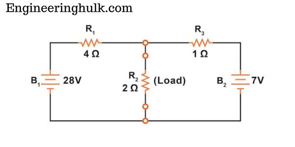
Thevenin’s theorem states that any linear two-terminal circuit, however complicated, behaves at its terminals exactly like a single voltage source Vth in series with a single resistance Rth. Vth is the open-circuit voltage across the two terminals, and Rth is the resistance seen looking back into the terminals with every independent source switched off. Once you have the pair, the load current is simply IL = Vth / (Rth + RL) for any load you connect.
The theorem is named after the French telegraph engineer Leon Charles Thevenin, who published it in 1883. It is part of every first-year B.Tech Basic Electrical Engineering course and is one of the most used tools in circuit analysis because it lets you study one branch without re-solving the whole network each time that branch changes.
Statement of Thevenin’s theorem
A linear, bilateral network containing voltage sources, current sources and resistances, viewed from any two terminals A and B, can be replaced by an equivalent circuit made of:
- an ideal voltage source Vth, equal to the open-circuit voltage between A and B, in series with
- a resistance Rth, equal to the resistance between A and B when all independent sources are replaced by their internal resistances (ideal voltage sources shorted, ideal current sources opened).
“Equivalent” means the terminal behaviour is identical: any load connected across A and B draws the same current and sees the same voltage in both circuits. What happens inside the original network (the power lost in its internal resistors, for example) is not represented.
How to apply Thevenin’s theorem: step-by-step
- Mark the load. Identify the element whose current or voltage you want (the load RL) and remove it, leaving terminals A and B open.
- Find Vth. Calculate the open-circuit voltage VAB using any method you like: voltage divider, Kirchhoff’s laws, mesh or nodal analysis.
- Find Rth. Deactivate every independent source: replace voltage sources with a short circuit and current sources with an open circuit. Then work out the equivalent resistance between A and B by series-parallel reduction.
- Draw the Thevenin equivalent. Vth in series with Rth, across terminals A and B.
- Reconnect the load. IL = Vth / (Rth + RL) and VL = IL × RL.
Tip: do not deactivate sources when finding Vth. Students often switch sources off too early and get Vth = 0.
Solved example of Thevenin’s theorem
Circuit: a 24 V battery with a 4 Ω resistor R1 in series feeds node C. A 12 Ω resistor R2 is connected from node C to the negative rail. From node C, a 3 Ω resistor R3 runs to terminal A; terminal B is the negative rail. A load RL is connected across A and B. Find the load current for RL = 6 Ω and RL = 12 Ω.
Step 1: Vth
With the load removed, no current flows in R3, so there is no drop across it and VAB equals the voltage across R2. R1 and R2 form a voltage divider:
Vth = 24 × 12 / (4 + 12) = 24 × 12 / 16 = 18 V
Step 2: Rth
Short the 24 V source. Looking in from A, R3 is in series with the parallel pair R1 and R2:
R1 || R2 = (4 × 12) / (4 + 12) = 48 / 16 = 3 Ω
Rth = 3 + 3 = 6 Ω
Step 3: Load current
| RL | IL = Vth / (Rth + RL) | VL | Power in load |
|---|---|---|---|
| 6 Ω | 18 / 12 = 1.5 A | 9 V | 1.5² × 6 = 13.5 W |
| 12 Ω | 18 / 18 = 1.0 A | 12 V | 1.0² × 12 = 12 W |
Check by solving the full circuit (RL = 6 Ω)
R3 + RL = 9 Ω, which is in parallel with R2: 12 × 9 / 21 = 5.143 Ω. Total resistance seen by the battery = 4 + 5.143 = 9.143 Ω, so the battery current is 24 / 9.143 = 2.625 A. The voltage at node C is 24 − 4 × 2.625 = 13.5 V, and the current through the 9 Ω branch is 13.5 / 9 = 1.5 A. It matches. Notice how the Thevenin route handled the second load value in one line, while the direct method would need the whole calculation again.
Circuits with dependent sources
A dependent (controlled) source cannot be switched off, because its value is set by a voltage or current elsewhere in the circuit. Leave it active and use one of these two methods for Rth:
- Test source method. Deactivate only the independent sources, apply a test voltage Vt (1 V is convenient) across A and B, calculate the current It it delivers, and take Rth = Vt / It. You can equally apply a 1 A test current and find the voltage.
- Open-circuit / short-circuit method. Keep all sources active, find Vth (open circuit) and the short-circuit current Isc with A and B shorted. Then Rth = Vth / Isc.
If the network has only dependent sources and no independent source, Vth = 0 and the equivalent is just Rth, found with a test source. With dependent sources Rth can even come out negative, which signals that the network supplies energy (an amplifier, for instance).
Thevenin to Norton conversion
Norton’s theorem is the dual of Thevenin’s: the same network can be replaced by a current source IN in parallel with a resistance RN. The two equivalents convert into each other with a single source transformation:
- IN = Vth / Rth (the short-circuit current)
- RN = Rth
- Vth = IN × RN
For the example above, IN = 18 / 6 = 3 A in parallel with 6 Ω. With a 6 Ω load, the current divides equally, giving 1.5 A in the load, the same answer. Use Thevenin when the load is in series with other elements; Norton is handier when loads are added in parallel.
Link with maximum power transfer
The maximum power transfer theorem is stated in Thevenin terms: a network delivers the most power to a resistive load when RL = Rth, and that maximum is
Pmax = Vth² / (4 Rth)
In the example, Rth = 6 Ω, so the 6 Ω load receives the most power: 18² / (4 × 6) = 324 / 24 = 13.5 W, matching the table. The 12 Ω load gets less (12 W). At maximum power transfer the efficiency is only 50%, because Rth dissipates as much as the load, which is why the idea suits signal and communication circuits (impedance matching) rather than power distribution.
Where Thevenin’s theorem is used
- Finding the current in one branch of a network when the load keeps changing, such as a variable resistor or a sensor.
- Bridge circuits: the current in the galvanometer of an unbalanced Wheatstone bridge.
- Transistor biasing: the base divider of a BJT amplifier is reduced to a Thevenin source before finding the base current.
- Power systems: short-circuit (fault) studies model the grid at a bus as a Thevenin voltage behind an equivalent impedance.
- Modelling real sources: a battery is a Thevenin equivalent of an EMF and internal resistance; the output stage of a logic gate in combinational circuits is often modelled the same way when checking fan-out and loading.
In AC circuits the theorem works the same way with phasors: Vth becomes a phasor voltage and Rth becomes an impedance Zth.
Limitations of Thevenin’s theorem
- Linear networks only. The network must obey superposition. Circuits with diodes, transistors in switching mode or saturating iron cores cannot be reduced exactly, although a linearised small-signal model can be.
- Terminal behaviour only. The equivalent gives the right load current and voltage, but not the power or efficiency inside the original network.
- Single frequency in AC. Zth depends on frequency, so an AC Thevenin equivalent is valid only at the frequency it was calculated for.
- Coupling to the load. The load must not be magnetically coupled to, or control a dependent source inside, the part being replaced.
For recorded lectures on network theorems, see the Basic Electrical Circuits courses on NPTEL.
FAQs
What is Thevenin’s theorem in simple words?
It says that any linear circuit, seen from two terminals, can be replaced by one voltage source Vth in series with one resistor Rth. The load connected to those terminals cannot tell the difference.
How do you find Thevenin resistance?
Remove the load, short all independent voltage sources, open all independent current sources, and calculate the resistance between the two terminals. With dependent sources present, apply a test source and use Rth = Vt / It, or use Rth = Vth / Isc.
What is the relation between Thevenin and Norton equivalents?
They describe the same network. The Norton current is IN = Vth / Rth, and the Norton resistance equals the Thevenin resistance.
Does Thevenin’s theorem work for AC circuits?
Yes. Replace resistances with impedances and voltages with phasors. The Thevenin impedance is valid only at the frequency used to calculate it.
Why can Thevenin’s theorem not be used for non-linear circuits?
The theorem depends on superposition, which holds only when voltages and currents are proportional. Diodes and other non-linear elements break that proportionality, so a single fixed Vth and Rth cannot describe them over their full range.