 EngineeringHulk
- Home
- Blog
- Manufacturing Engineering
- Pipe Bender / Tube Bender Machine: Working, Types and Applications
Pipe Bender / Tube Bender Machine: Working, Types and Applications
On this page
- How does a pipe bender machine work?
- Main parts of a rotary draw tube bender
- Types of pipe and tube bending
- Centreline radius and the “D of bend”
- Worked example: bend length and wall thinning
- Common bending defects and their causes
- Advantages and limitations of tube bending
- Applications of pipe benders
- FAQs
- Related Topics on EngineeringHulk
A pipe bender or tube bender is a machine that bends a pipe or tube to a set angle around a fixed centreline radius (CLR) while supporting the wall, so the cross-section does not flatten, wrinkle or kink. The main methods are rotary draw bending (with or without a mandrel), compression bending, ram (press) bending and roll bending. Which one you use depends on how tight the bend is compared with the tube diameter, how thin the wall is, and how accurate the part must be.
How does a pipe bender machine work?
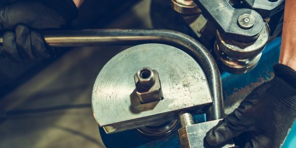
When a tube bends, the material on the outside of the bend is stretched and the material on the inside is compressed. Stretching thins the outer wall and pulls it towards the centre, which makes the round section go oval. Compression thickens the inner wall and, if it has nowhere to go, it buckles into wrinkles. A tube bender works by forcing the tube to follow a grooved die of the exact radius while other tools hold the wall in shape from outside and, when needed, from inside. The same bending mechanics as a beam apply: fibres farther from the neutral axis see more strain, which is explained in bending stress.
Pipe and tube are sized differently. Pipe is ordered by nominal bore (NB or NPS) and a wall schedule, so a 25 NB pipe has an outside diameter of 33.4 mm. Tube is ordered by its actual outside diameter and wall thickness. Bending tooling is always matched to the real OD.
Main parts of a rotary draw tube bender
| Part | Job |
|---|---|
| Bend die (radius die) | Rotating die with a groove of the tube’s OD; its radius sets the CLR |
| Clamp die | Grips the tube against the straight part of the bend die so the tube is drawn round as the die rotates |
| Pressure die | Presses the tube into the bend die groove and reacts the bending load; often moves forward with the tube (boost) to reduce outer-wall thinning |
| Wiper die | Sits just behind the tangent point on the inside of the bend and fills the gap there, stopping wrinkles on thin-wall, tight bends |
| Mandrel | Plug or ball-link mandrel inside the tube at the bend zone; keeps the tube round and prevents collapse |
| Carriage and controller | On CNC benders, a carriage feeds the tube (length), rotates it (plane of bend) and the controller sets the bend angle, so a whole 3D exhaust or handrail is bent in one sequence |
Types of pipe and tube bending
Rotary draw bending
The tube is clamped to the bend die, and the die rotates, drawing the tube around it while the pressure die supports it. It is the most accurate and repeatable method, gives a constant CLR, and handles tight bends down to about 1D with a mandrel and wiper. Used for roll cages, handrails, furniture frames, aircraft hydraulic lines and automotive exhausts.
Mandrel bending
Mandrel bending is rotary draw bending with a mandrel inside the tube. It is needed when the wall is thin relative to the diameter or when the bend is tight. The result is a smooth, round bend with near-full flow area, which matters for exhaust and intake pipes and for fluid lines where a flattened section adds pressure drop.
Compression bending
The bend die stays still. The tube is clamped at one end and a follower block or roller is swung around the die, pressing the tube into the groove. It is simple and quick to set up, and is the principle of most hand-operated conduit and plumbing benders. It cannot use a mandrel, so it suits thicker walls and generous radii.
Ram (press) bending
A ram pushes a shaped die into the middle of the tube, which rests on two pivoting wing dies. It is the cheapest and fastest method, used for heavy pipe and hydraulic-jack benders on site. The tube is unsupported inside and out, so it distorts most; not suitable for thin wall or precise work.
Roll bending
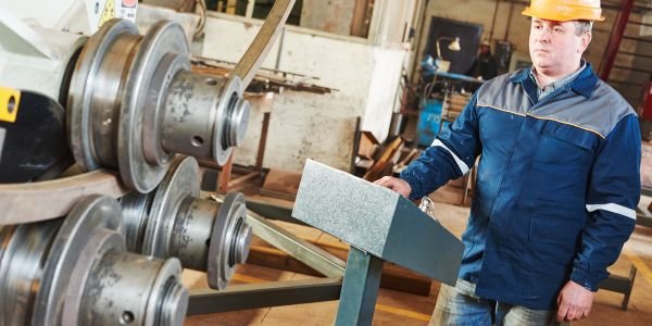
The tube passes back and forth through three rolls (a pyramid arrangement). Moving the centre roll down makes the curve tighter. It produces large radii, full circles, coils and spirals, for example structural arches, handrail curves on stairs and pipe rings. It cannot make tight bends.
Centreline radius and the “D of bend”
The centreline radius (CLR) is the radius of the bend measured to the centre of the tube. Bends are described by the D of bend: CLR divided by tube OD. A 25.4 mm OD tube bent on a 50.8 mm CLR is a “2D” bend. The smaller the D of bend, the more severe the bend.
The second ratio benders use is the wall factor: OD divided by wall thickness. A high wall factor (thin wall) together with a low D of bend is the hardest combination and is where mandrels and wiper dies become necessary. Tooling makers publish charts of D of bend against wall factor that show which tools are required.
Worked example: bend length and wall thinning
Tube: 25.4 mm OD × 1.6 mm wall, bent 90° on a 50.8 mm CLR (2D).
1. Developed length of the bend. The centreline neither stretches nor shrinks (approximately), so the tube length consumed by the bend is the arc length along the centreline:
L = CLR × θ (in radians) = 50.8 × (90 × π / 180) = 50.8 × 1.5708 = 79.8 mm.
Add the two straight legs to get the cut length of the blank. For a 45° bend on the same die the arc is half, 39.9 mm.
2. Outer-fibre strain. The outside of the tube lies on a radius of CLR + OD/2 = 50.8 + 12.7 = 63.5 mm. Its strain compared with the centreline is (63.5 − 50.8) / 50.8 = 12.7 / 50.8 = 0.25, or 25%. In general it equals 1 / (2 × D of bend), so a 1D bend stretches the outer fibre by 50%. That is why tight bends need ductile material.
3. Rough wall thinning. If the metal’s volume and width stay the same, thickness falls in proportion to the stretch: touter ≈ t × CLR / (CLR + OD/2) = 1.6 × 50.8 / 63.5 = 1.28 mm, about 20% thinning. The inner wall thickens to about 1.6 × 50.8 / 38.1 = 2.13 mm. Real bends thin less than this simple estimate because the neutral axis moves towards the inside of the bend and a boosted pressure die pushes material into the bend, but the estimate shows the trend clearly.
Common bending defects and their causes
| Defect | What you see | Usual fix |
|---|---|---|
| Ovality (flattening) | Round section becomes oval; ovality = (Dmax − Dmin) / Dnominal × 100% | Mandrel, correct groove fit, larger CLR |
| Wrinkling | Ripples on the inside of the bend | Wiper die, mandrel, more pressure-die force |
| Excess wall thinning / cracking | Thin or split outer wall | Larger CLR, pressure-die boost, annealed or more ductile material |
| Kinking / collapse | Sharp fold in the bend | Mandrel, lower D-of-bend limit, check clamp slip |
| Springback | Bend angle opens after release; radius also grows slightly | Over-bend by a measured amount; CNC benders store a correction per material |
| Marks and scoring | Scratches from dies | Lubricate mandrel and wiper, polished tooling |
Springback happens because part of the bending strain is elastic. When the tooling lets go, that elastic part recovers and the angle opens a little. Higher strength materials such as stainless steel and titanium spring back more than mild steel or copper. The practical method is a test bend: bend to 90°, measure the actual angle, and add the difference as over-bend for production.
Advantages and limitations of tube bending
- Fewer joints: one bent tube replaces a straight tube plus welded or threaded elbows, so there are fewer leak paths and less welding.
- Smoother flow: a bend has lower pressure loss than a sharp elbow.
- Lighter, neater assemblies: important in vehicles and furniture.
- Limitations: each tube size and CLR needs its own tooling set; very tight bends need mandrels and expert setup; the wall thins on the outside, which must be allowed for in pressure piping.
Applications of pipe benders
- Automotive exhausts, brake and fuel lines, seat frames and roll cages.
- HVAC and refrigeration copper lines, boiler and heat-exchanger tubes.
- Hydraulic and pneumatic lines in machinery and aircraft.
- Handrails, balustrades, bicycle and gym-equipment frames, steel furniture.
- Electrical conduit and plumbing on site (hand and hydraulic benders).
- Structural arches and curved members (roll bending).
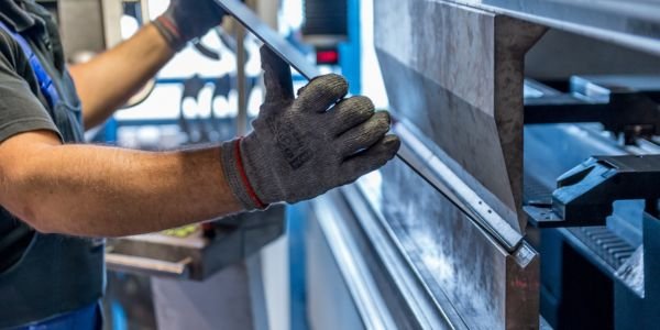
Tube bending is one branch of metal forming. For flat stock, see sheet metal fabrication, where press-brake bending plays the same part.
FAQs
What is the difference between a pipe bender and a tube bender?
The machines work the same way. The difference is sizing: pipe is specified by nominal bore and schedule, tube by exact outside diameter and wall. Tube benders usually handle thinner walls and tighter, more precise bends; pipe benders handle heavier wall sizes.
What is CLR in tube bending?
CLR (centreline radius) is the bend radius measured to the centre of the tube. Divided by the tube OD it gives the “D of bend”, for example a 2D bend has a CLR twice the OD.
Why is a mandrel used in pipe bending?
A mandrel supports the tube from inside at the bend zone, preventing flattening, wrinkling and collapse. It is needed for thin-wall tubes and tight bends.
How do you calculate the length of a pipe bend?
Multiply the centreline radius by the bend angle in radians. A 90° bend on a 50.8 mm CLR uses 50.8 × 1.5708 = 79.8 mm of tube.
What causes springback in tube bending?
The elastic part of the bending strain recovers when the tube is released, so the angle opens slightly. It is corrected by over-bending, with the amount found from a test bend for each material and size.
Related Topics on EngineeringHulk
Keep reading
Punching Machine: Working, Types, Force Calculation and Applications
Punching machine explained: how a punch and die shear a hole, punch-die clearance, types of punching machinery, a worked punching force example, defects.

CNC Mills: Working, Types, Programming and Applications
How a CNC mill works: VMC vs HMC, 3/4/5-axis types, spindle, table, ATC and controller, a G-code example, work offsets and applications.

Gate Valve: Working, Parts, Types, Standards and Applications
A gate valve is an isolation valve for fully open or fully closed duty. Its parts, working, wedge and stem types, standards and why never to throttle it.
Magneto Ignition System: Working Principle, Parts, Types and Applications
A magneto ignition system makes its own high-voltage spark from an engine-driven magnet, with no battery. Working, parts, types, timing and applications.
Injection Molding Machine: Parts, Working, Types and Advantages
How an injection molding machine works: injection unit, clamping unit and mold, the cycle, hydraulic vs electric types, clamping force and defects.
Waterjet Machine: Types, Working, Parts and Benefits
How a waterjet machine works: pure vs abrasive waterjet, intensifier pump, orifice, mixing tube, kerf and taper, a jet velocity example, pros and cons.