A grinder machine removes material with a rotating abrasive wheel whose thousands of hard grains each act as a very small cutting tool, taking chips only a few micrometres thick. That is why grinding reaches finishes of 0.2 to 0.8 micron Ra and tolerances near 0.005 mm, and also why it needs roughly 20 to 60 J of energy per cubic millimetre against 2 to 9 J/mm3 for turning or milling the same steel. The machine can be a precision production grinder or the 100 mm angle grinder in a fabrication shop; the cutting physics is the same in both.
How abrasive cutting actually works
A grinding wheel is not one cutting edge. It is a bonded block of abrasive grains, and only the grains sitting proud of the bond at the contact arc do any work. Each of those grains is a tiny, randomly oriented cutting tool, and its geometry is nothing like a milling cutter tooth.
- Very high negative rake. A grain presents whatever face the bond happened to leave pointing outward, so effective rake angles are commonly in the range of -30 to -60 degrees. A milling cutter for steel works at about +5 to +15 degrees positive rake.
- Random spacing and random height. Grains sit at different heights, so they do not all cut. Some only rub, some plough the surface aside without separating a chip, and only the tallest ones actually cut.
- Tiny chips. Undeformed chip thickness in precision grinding is usually under 10 micrometres and often around 1 to 5. A milling tooth in the same job takes a chip 0.05 to 0.3 mm thick, that is 10 to 100 times more.
So the material in front of a grain goes through three stages as the grain sinks in: rubbing (elastic deflection, no removal), ploughing (plastic flow, material pushed to the sides into ridges) and finally cutting (a chip forms and leaves). Only the third stage removes metal. The first two produce heat and nothing else, and they are a large part of what makes grinding expensive in energy terms.
Why grinding needs so much more specific energy
Specific energy, u, is the energy spent per unit volume of material removed, in J/mm3. It is the cleanest way to compare grinding with ordinary machining.
| Process (medium carbon steel) | Typical specific energy | Why |
|---|---|---|
| Turning or milling | About 2 to 9 J/mm3 | Positive rake, chips 0.1 mm thick, most of the energy goes into shearing a large chip cleanly. |
| Conventional grinding | About 20 to 60 J/mm3 | Negative rake, micron chips, plus rubbing and ploughing that remove nothing. |
| Fine or creep-feed grinding of superalloys | Up to 200 J/mm3 and beyond | Finer grit, smaller chips, tougher material, long contact arc. |
The main driver is the size effect: as the chip gets thinner, the energy per unit volume rises sharply, because the surface area being rubbed and the edge radius of the grain stay the same while the chip shrinks. A grain with a 10 micron edge radius trying to take a 2 micron chip is mostly ploughing, not cutting.
The practical consequence matters more than the number. Almost all of that specific energy ends up as heat in a very small contact zone, which is the source of every thermal problem further down this page.
Grinding process parameters and formulas
Four numbers control a grinding operation: wheel speed, work speed, depth of cut and the width being ground.
Wheel peripheral speed
V = π D N / 60000, with D in mm, N in rpm and V in m/s.
A 250 mm vitrified wheel at 2400 rpm gives V = 3.1416 x 250 x 2400 / 60000 = 31.4 m/s. Typical ranges: conventional vitrified wheels 25 to 35 m/s, high-speed wheels 45 to 60 m/s, CBN and diamond wheels on suitable machines 60 to 120 m/s. A 230 mm cut-off disc on a portable grinder at 6600 rpm also works out at about 79 m/s, which is why those discs are rated to 80 m/s.
Work speed and depth of cut
Work speed (vw) is how fast the job passes the wheel: roughly 10 to 30 m/min on surface grinding, 15 to 60 m/min on cylindrical grinding. Depth of cut (d) is small by the standards of any other process: 0.005 to 0.05 mm per pass in ordinary precision grinding, dropping to 0.002 mm or less on spark-out passes.
Material removal rate with a worked example
MRR = d x w x vw, where d is depth of cut, w is the width of cut and vw is work speed.
Take a surface grinder finishing a 20 mm wide face, depth of cut 0.02 mm, table speed 15 m/min (250 mm/s):
- MRR = 0.02 x 20 x 250 = 100 mm3/s, which is 6000 mm3/min.
- An end mill on the same part could clear 20,000 to 60,000 mm3/min without difficulty.
That single comparison explains the entire place of grinding in a process plan. You rough with a cutting tool and finish with abrasive, because abrasive is slow and accurate.
Chip thickness relation
The average undeformed chip thickness t links the parameters to what one grain feels:
t = √[ (4 vw) / (vs C r) x √(d / D) ]
where vs is wheel speed, C is the number of active grains per unit area of wheel surface, r is the ratio of chip width to chip thickness (usually taken as 10 to 20), d is depth of cut and D is wheel diameter. Read the relation rather than the algebra: chip thickness falls when you raise wheel speed, use a finer wheel (higher C) or use a larger wheel, and rises when you raise work speed or depth of cut. A thinner chip means better finish and lower forces per grain, but higher specific energy and more heat per unit of metal removed.
Grinding forces, power and the heat problem
Grinding has a tangential force Ft acting along the wheel surface and a normal force Fn pushing wheel and work apart. Because of those negative rake angles and all the ploughing, the normal force is typically 1.5 to 3 times the tangential force, the opposite of the ratio in turning. That large normal force is why a slender shaft deflects away from the wheel and comes out with a taper, and why spark-out passes exist at all.
Power follows directly: P = Ft x V, and equivalently P = u x MRR.
Continuing the example above at u = 40 J/mm3 and MRR = 100 mm3/s:
- P = 40 x 100 = 4000 W = 4 kW at the wheel.
- Ft = P / V = 4000 / 31.4 = 127 N, and Fn is therefore around 250 N.
Four kilowatts to shave twenty microns off a small face. Nearly all of it turns into heat, and in shallow-cut grinding with aluminium oxide wheels something like 60 to 85% of that heat enters the workpiece rather than the chips or the wheel. Flash temperatures at the grain contact reach well over 1000 degrees Celsius.
The damage that follows has names worth knowing:
- Temper burn – the surface layer of hardened steel is tempered back, hardness drops, and a blue or brown oxide colour appears.
- Rehardening burn – the surface passes the austenitising temperature and is quenched by the coolant, leaving brittle untempered martensite (a white layer) over a soft tempered layer.
- Residual tensile stress and thermal cracks – the heated layer is restrained by the cold bulk, so it ends up in tension. Tensile residual stress at the surface is a direct loss of fatigue life on parts like bearing races and gear teeth.
Grinding fluid is not optional cooling; it is a process parameter. A water-based emulsion or synthetic fluid is chosen mainly to carry heat away and flush swarf out of the wheel face; neat oil lubricates better, cuts the friction component of the energy, improves finish and wheel life, and is normal in gear, thread and form grinding. Delivery matters as much as the fluid: a wheel spinning at 30 m/s drags a boundary layer of air with it, so a slow dribble of coolant never reaches the contact arc. The nozzle jet velocity should be close to the wheel speed, aimed into the contact, often with a scrubber nozzle to clear the wheel face.
Wheel wear and the G-ratio
The wheel is consumed as it works. Grains fracture, bonds break and grains pull out, and the wheel loses both size and form. The standard measure of this is the grinding ratio or G-ratio:
G = volume of workpiece material removed / volume of wheel material lost
A G-ratio of 40 means the wheel gives up 1 mm3 of itself for every 40 mm3 of steel removed. Typical values span a very wide band:
- Rough snagging and cut-off with resin-bonded wheels: roughly 1 to 10. The disc is expected to be a consumable.
- Precision grinding of steel with vitrified aluminium oxide: commonly 20 to 80.
- CBN wheels on hardened steel: often in the hundreds to several thousand, which is the main economic argument for a wheel that costs many times more.
Chasing the highest possible G-ratio is a mistake. A wheel that refuses to wear is a wheel whose dull grains are not breaking away, and dull grains mean rising forces, rising power and burn. The wheel has to break down at a controlled rate, which is what grade, structure and dressing practice are actually tuning.
Types of grinding machines: the short version
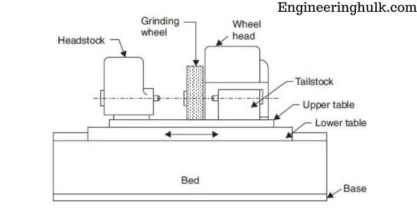
Production grinders are classified by the surface they finish: surface grinders for flat faces, cylindrical and centreless grinders for round parts, internal grinders for bores, tool and cutter grinders for resharpening cutters, plus jig, gear and CNC machines for position-critical and form work. Each has its own accuracy band, workholding and set-up logic, and the wheel marking code (abrasive, grit, grade, structure, bond) decides which wheel you fit. That whole taxonomy, with the wheel specification system, tolerances and dressing practice, is covered separately in types of grinding machines.
Anatomy of a bench or pedestal grinder
This is the machine most workshops actually own. A pedestal grinder is the same machine on a floor column instead of a bench.
| Part | Function | Typical detail |
|---|---|---|
| Induction motor | Drives both wheels directly on the shaft ends | 0.25 to 1 kW, 2850 rpm on 50 Hz supply. No belt, no gearbox. |
| Two wheels | Coarse wheel for stock removal, fine wheel for finishing | 150 or 200 mm diameter, 20 to 25 mm wide. A 200 mm wheel at 2850 rpm runs at about 29.8 m/s. |
| Flanges and blotters | Clamp the wheel evenly and spread the clamping load | Matched flanges of equal diameter, at least one third of the wheel diameter, with paper blotters between flange and wheel. |
| Wheel guard | Contains fragments if a wheel bursts | Must enclose the wheel except for the working opening. |
| Work rest (tool rest) | Supports the workpiece so it cannot be dragged into the gap | Set to within 3 mm of the wheel face and reset as the wheel wears down. |
| Tongue guard / spark arrester | Closes the gap above the wheel | Adjusted to within about 6 mm of the wheel. |
| Eye shield and water pot | Deflects sparks; lets the operator dip the work | The shield never replaces a face shield. Dipping controls temper colour on tool bits. |
Anatomy of an angle grinder
The hand-held angle grinder is a universal motor driving a right-angle bevel gear pair, which turns the drive through 90 degrees and reduces speed while raising torque at the spindle.
- Universal motor, 500 W to about 2600 W, running fast and light so the tool stays portable.
- Bevel gear head with the spindle, an M14 thread on most 100 to 230 mm machines.
- Inner flange, disc, outer lock nut. The outer nut is reversible: flat face outward for thin cutting discs, recessed face outward for thicker depressed-centre discs.
- Adjustable guard, rotated so sparks and any fragments go away from the operator’s body.
- Side handle, screwed into whichever of the two or three bosses suits the cut.
- Spindle lock button, for changing discs with the tool unplugged.
Sizes and speeds follow from the 80 m/s disc rating: a 100 mm machine runs at about 11,000 to 12,000 rpm, 115 and 125 mm at 10,000 to 11,000 rpm, 180 mm at around 8,500 rpm and 230 mm at around 6,600 rpm. Better machines add a soft-start, constant-speed electronics and a brake, plus a restart lock so the tool does not come alive when power returns.
Hand-held grinder safety in detail
An angle grinder disc that bursts at 11,000 rpm throws fragments with real energy. These rules are the ones that get broken.
- Match the speed rating to the machine. Every bonded disc is marked with a maximum operating speed in rpm and in m/s. That rpm figure must be equal to or higher than the no-load speed on the tool’s nameplate. A 125 mm disc rated 12,200 rpm is safe on a 125 mm grinder; the same disc on a small high-speed die grinder is not.
- Check the disc size and bore. Never fit a larger disc by removing the guard, and never open out the bore. The guard is sized to the disc.
- Read the expiry date. Resin-bonded discs carry a use-by date, normally three years from manufacture, because the bond degrades. An old disc from the back of a drawer is scrap.
- Ring test the vitrified wheels. For bench and pedestal wheels, suspend the wheel on a pin, tap it gently about 45 degrees either side of the vertical centreline with a light non-metallic implement, and listen. A sound wheel gives a clear ring; a dull or dead thud means a crack, and the wheel goes in the bin. The test only works on dry vitrified wheels, so it is not valid for resin-bonded, reinforced or very thin discs, which are inspected visually instead.
- Never use a cutting disc for side grinding. A thin type 41 cut-off wheel is reinforced for radial loads only. Push on its face to dress an edge and it flexes, snatches and shatters. Grinding is done with a thicker depressed-centre type 27 wheel; cutting is done with the edge of a cut-off wheel, in a straight line, never twisted in the kerf.
- Keep the guard on, always. The single most common serious-injury factor with these tools is a removed or rotated-away guard.
- Run a new disc for a minute at full speed with the tool pointed away from people, before touching the work.
- Control kickback. Two hands, side handle fitted, a firm stance, and never let the upper quadrant of the disc catch an edge. Cut with the disc rotating away from you where the design allows, and let the tool reach full speed before contact.
- PPE that matches the hazard. Face shield over impact-rated safety glasses, hearing protection (these tools sit near 95 to 100 dB), close-fitting clothing, leather gloves, and respiratory protection when cutting concrete, stone or anything producing silica dust. Clear or screen the area: sparks travel several metres and start fires.
- Handle the tool sensibly. Unplug before changing a disc, never lock the trigger on, and never put the grinder down until the disc has stopped spinning.
On the fixed machines, the additional points are workholding and the gaps. Small parts get held in fixtures or a magnetic chuck rather than fingers, and the work rest and tongue guard gaps are reset every time the wheel is dressed down.
Applications of grinding machines
- Finishing hardened parts. Anything above about 45 HRC is grinding work, because cutting tools struggle there: bearing races, gear teeth after heat treatment, die and mould surfaces, hydraulic spool valves.
- Size and form accuracy. Crankshaft and camshaft journals, spindle tapers, piston pins, injector bodies, where 0.005 mm and a fine finish decide whether the part works.
- Surface finish for function. Sealing faces, sliding faces and fatigue-critical surfaces, where the finish controls leakage, friction or crack initiation.
- Cutting tool manufacture and resharpening, including carbide tooling that only diamond wheels will touch.
- Fabrication and site work. Angle grinders for cutting bar and section, removing weld spatter, chamfering plate edges before welding, cleaning up castings and cutting tiles or concrete with the right disc.
- Deburring and snagging of castings and forgings on pedestal grinders and swing-frame machines, and preparation of punched and sheared edges.
Advantages and limitations
| Advantages | Limitations |
|---|---|
| Tolerances near 0.005 mm and finishes of 0.2 to 0.8 micron Ra in normal production. | Material removal rate is a fraction of milling, so it is a finishing process, not a roughing one. |
| Machines material of any hardness, including hardened steel, carbide and ceramics. | Very high specific energy, so the power bill per kilogram removed is high. |
| Corrects distortion left by heat treatment, which no pre-hardening operation can do. | Heat concentrates in the surface and can cause burn, untempered martensite and tensile residual stress. |
| Light cutting forces per grain suit thin, slender and delicate parts. | The wheel wears and loses form, so dressing and truing are recurring, skilled work. |
| The same principle scales from a 500 W hand tool to a CNC production grinder. | Fine metallic and abrasive dust, plus coolant mist, need extraction and disposal. |
References
- NPTEL – Manufacturing Processes, IIT lecture series (abrasive machining, grinding mechanics and thermal aspects).
- Bureau of Indian Standards, IS 551, marking system for bonded abrasive products.
- Manufacturer catalogues and tool nameplates for portable grinder speeds and bonded disc speed ratings (80 m/s class).
FAQs
What is a grinder machine and how does it work?
A grinder machine is a machine tool that removes material using a rotating abrasive wheel. Each exposed abrasive grain acts as a small cutting tool with a strongly negative rake angle, taking chips only a few micrometres thick. Because thousands of grains cut at once at 25 to 60 m/s, the process produces tight tolerances and fine finishes rather than fast stock removal.
How do you calculate material removal rate in grinding?
MRR = depth of cut x width of cut x work speed. For a surface grinder taking 0.02 mm depth across a 20 mm width at a table speed of 250 mm/s, MRR = 0.02 x 20 x 250 = 100 mm3/s, or 6000 mm3/min. Multiplying MRR by the specific energy gives the power needed at the wheel.
Why does grinding generate so much heat?
Grinding uses about 20 to 60 J/mm3 against 2 to 9 J/mm3 for turning or milling, because the chips are microns thick and much of the grain contact only rubs and ploughs instead of cutting. Almost all that energy becomes heat in a tiny contact zone, and in shallow-cut grinding roughly 60 to 85% of it flows into the workpiece, which is why grinding fluid and its delivery are part of the process settings.
What is the G-ratio of a grinding wheel?
The G-ratio is the volume of workpiece material removed divided by the volume of wheel material worn away. Rough cut-off work with resin discs gives roughly 1 to 10, precision grinding of steel with vitrified aluminium oxide commonly 20 to 80, and CBN wheels can reach several hundred to several thousand. A very high value is not always good, since a wheel that will not break down goes dull and burns the work.
Can you use a cutting disc for grinding on an angle grinder?
No. A thin cut-off disc is reinforced for loads applied at its edge, not on its face. Side grinding with one makes it flex and shatter at full speed. Use a depressed-centre grinding wheel for grinding, keep the guard fitted, and check that the disc’s marked maximum rpm is at least the tool’s no-load speed.