Table of Contents
Carnot cycle Introduction:
The Carnot cycle is a thermodynamic cycle that was introduced by French physicist Sadi Carnot in 1824. It is a theoretical model for a heat engine that operates between two heat reservoirs at different temperatures. This cycle is an idealized model of the heat engine, and it is used to describe the maximum efficiency that any engine can achieve.
Carnot cycle and its processes have been an integral part of thermodynamics and are widely used in engineering and science applications. The Carnot cycle is an idealized thermodynamic cycle, consisting of four reversible processes that work together to produce the maximum possible efficiency.
What is the Carnot Cycle?
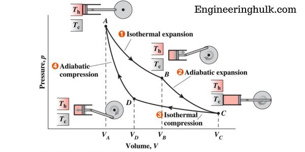
The Carnot cycle is a thermodynamic cycle that consists of four processes: isothermal compression, adiabatic compression, isothermal expansion, and adiabatic expansion. The cycle is depicted on a P-V diagram, where P is the pressure and V is the volume.
The cycle starts at point A on the diagram, where the gas is in thermal equilibrium with a high-temperature reservoir. The gas expands isothermally to point B, where it is in thermal equilibrium with a low-temperature reservoir.
The gas then undergoes adiabatic compression to point C, where it is again in thermal equilibrium with the high-temperature reservoir. Finally, the gas undergoes isothermal compression to point A, where the cycle is completed.
The Four Processes of the Carnot Cycle
The Carnot cycle consists of four processes, two isothermal and two adiabatic, which are carried out in the following order:
The Carnot cycle is a theoretical thermodynamic cycle that is often used as a benchmark for the maximum possible efficiency of a heat engine. It consists of four processes: isothermal expansion, adiabatic expansion, isothermal compression, and adiabatic compression.
The P-V (pressure-volume) and T-S (temperature-entropy) diagrams of the Carnot cycle are useful tools for understanding the thermodynamic processes that occur in the cycle.
P-V Diagram of Carnot Cycle:
The P-V diagram of the Carnot cycle is a graphical representation of the changes in pressure and volume that occur during the cycle. The cycle consists of four processes:
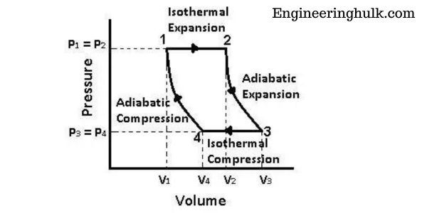
1. Isothermal Expansion (Process 12):
During this process, the gas in the system expands isothermally (at constant temperature) from volume V1 to volume V2. As the gas expands, its pressure decreases, and the work done by the gas is given by the area under the curve on the P-V diagram between points A and B.
2. Adiabatic Expansion (Process 23):
During this process, the gas expands adiabatically (without heat transfer) from volume V2 to volume V3. As the gas expands, its temperature decreases, and its pressure also decreases. The work done by the gas during this process is given by the area under the curve on the P-V diagram between points B and C.
3. Isothermal Compression (Process 34):
During this process, the gas is compressed isothermally (at constant temperature) from volume V3 to volume V4. As the gas is compressed, its pressure increases and the work done on the gas is given by the area under the curve on the P-V diagram between points C and D.
4. Adiabatic Compression (Process 41):
During this process, the gas is compressed adiabatically (without heat transfer) from volume V4 to volume V1. As the gas is compressed, its temperature increases and its pressure also increases. The work done on the gas during this process is given by the area under the curve on the P-V diagram between points D and A.
T-S Diagram of Carnot Cycle:
The T-S diagram of the Carnot cycle is a graphical representation of the changes in temperature and entropy that occur during the cycle. The cycle consists of four processes:
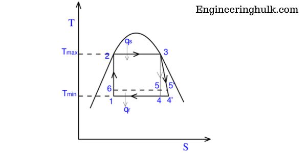
1. Isothermal Expansion (Process 12):
During this process, the gas in the system expands isothermally (at constant temperature) from point 1 to point 2. As the gas expands, its entropy increases and the heat is absorbed by the gas.
2. Adiabatic Expansion (Process 23):
During this process, the gas expands adiabatically (without heat transfer) from point 2 to point 3. As the gas expands, its temperature decreases, and its entropy also decreases.
3. Isothermal Compression (Process 34):
During this process, the gas is compressed isothermally (at constant temperature) from point 3 to point 4. As the gas is compressed, its entropy decreases, and heat is released from the gas.
4. Adiabatic Compression (Process 41):
During this process, the gas is compressed adiabatically (without heat transfer) from point 4 to point 1. As the gas is compressed, its temperature increases, and its entropy also
The efficiency of the Carnot Cycle:
The efficiency of the Carnot cycle can be defined as the ratio of the work output to the heat input. Mathematically, it can be expressed as:
Efficiency = (Work Output / Heat Input) x 100%
The maximum efficiency of the Carnot cycle can be determined by the temperatures of the heat source and heat sink. According to the Carnot theorem, the efficiency of the Carnot cycle is given by:
Efficiency = (Th – Tc) / Th x 100%
where Th is the absolute temperature of the high-temperature heat source, and Tc is the absolute temperature of the low-temperature heat sink.
It can be seen from the above equation that the efficiency of the Carnot cycle depends only on the temperature difference between the heat source and the heat sink. This means that the efficiency of the Carnot cycle can be increased by increasing the temperature difference between the heat source and heat sink.
Importance of Efficiency of Carnot Cycle:
The efficiency of the Carnot cycle has great significance in the field of thermodynamics. It sets a theoretical upper limit on the efficiency of any heat engine that operates between two temperature limits. This means that no heat engine can have an efficiency greater than that of the Carnot cycle when operating between the same temperature limits.
Moreover, the Carnot cycle provides a standard for comparing the efficiency of real-world heat engines. The efficiency of real-world heat engines is always less than that of the Carnot cycle due to various irreversibilities such as friction and heat losses.
Applications of the Carnot Cycle:
The Carnot cycle has several applications in real-world systems, including:
1. Heat Engines: The Carnot cycle is an idealized model for a heat engine. It provides a theoretical maximum efficiency for any heat engine that operates between two temperatures. The efficiency of a Carnot engine is given by the equation:
Efficiency = 1 – (Tc/Th)
Where Tc is the temperature of the cold reservoir, and Th is the temperature of the hot reservoir. This equation shows that the efficiency of a Carnot engine increases with an increase in the temperature difference between the hot and cold reservoirs.
2. Refrigeration and Air Conditioning: The Carnot cycle is also used in refrigeration and air conditioning systems. These systems use a cycle that is similar to the Carnot cycle, but with the roles of the hot and cold reservoirs reversed. The cycle is used to extract heat from a low-temperature reservoir and transfer it to a high-temperature reservoir.
This process requires energy input, and the efficiency of the system is given by the coefficient of performance (COP). The COP is defined as the ratio of the heat removed from the low-temperature reservoir to the energy input to the system. The Carnot cycle provides the theoretical maximum COP for any refrigeration or air conditioning system.
3. Power Generation: The Carnot cycle is also used in power generation systems, such as steam turbines. These systems use a cycle that is similar to the Carnot cycle but with the addition of a heat source and a heat sink. The heat source is used to generate steam, which drives a turbine to produce electricity.
The heat sink is used to condense the steam back into the water. The efficiency of the system is given by the Carnot efficiency, which is the maximum theoretical efficiency that any power generation system can achieve.
Also, read the venturi meter


[…] Also, read the Carnot cycle […]