 EngineeringHulk
- Home
- Blog
- Manufacturing Engineering
- Brazing Process: Joint Design, Filler Metals, Steps and Applications
Brazing Process: Joint Design, Filler Metals, Steps and Applications

On this page
- What is the brazing process?
- Joint design and clearance
- Surface preparation
- Flux, self-fluxing filler or a protective atmosphere
- Heating methods
- Brazing filler metals (AWS A5.8 classes)
- Step-by-step brazing procedure
- Brazing defects and inspection
- Advantages and limitations of brazing
- Applications of brazing
- References
- FAQs
- Related Topics on EngineeringHulk
Brazing is a joining process in which a filler metal with a liquidus above 450 °C, but below the melting point of the parts, is melted and drawn into a tight joint by capillary action. The base metal never melts. Most brazing is done at roughly 580 to 1,200 °C with silver, copper-phosphorus, copper, aluminium-silicon or nickel filler metals, and it is the standard way to join copper refrigerant lines, aluminium heat exchangers and carbide tool tips.
This page covers the brazing process itself: how a joint is designed, prepared, heated and inspected, and which filler to pick. If you only want to know how brazing differs from soldering, read the side-by-side comparison on brazing vs soldering. In short, the dividing line is the 450 °C filler liquidus set by the American Welding Society, and brazing gives much stronger joints.
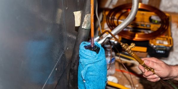
What is the brazing process?
Three things have to happen for a braze to work:
- The joint is heated, not the filler. Both parts are brought up to brazing temperature, which is a little above the filler’s liquidus.
- The filler wets the surface. Molten filler spreads over clean, oxide-free metal and forms a thin metallurgical bond with it by diffusion. On oxidised or greasy metal it balls up instead.
- Capillary action pulls it in. Once it wets both faces, the filler is sucked into the narrow gap between them, even upwards or around a tube, and leaves a neat fillet at each edge.
Joint design and clearance
Capillary flow depends on the gap. Too tight and the filler cannot enter; too wide and capillary pull is lost, the gap fills with a thick layer of weaker filler, and voids form.
| Situation | Typical clearance per side |
|---|---|
| Silver (BAg) filler with paste flux, torch or induction | 0.05 to 0.13 mm (0.002 to 0.005 in) |
| Strongest silver-brazed joint in maker’s tests | About 0.04 mm (0.0015 in) |
| Copper-phosphorus (BCuP) on copper tube | 0.025 to 0.13 mm |
| Nickel (BNi) filler, furnace brazing | 0.05 to 0.13 mm |
| Vacuum or controlled-atmosphere brazing without flux | Close to zero up to about 0.05 mm; copper brazing of steel often uses a light press fit |
Flux-free furnace brazing tolerates tighter gaps because there is no flux that has to be pushed out of the joint ahead of the filler.
Lap joints, not butt joints
Brazing filler is weaker than steel, so the joint gets its strength from area. The usual choice is a lap joint (or a tube pushed into a socket) with an overlap of at least three times the thickness of the thinner member. A butt joint has only the cross-section of the part to bond on and is avoided wherever the load matters. A scarf joint, with the ends cut at a shallow angle, is a compromise when the thickness must not change.
Worked example: overlap. A copper tube with a 1.2 mm wall needs a minimum overlap of 3 × 1.2 = 3.6 mm. Standard fittings give far more socket depth than that, which is why an overloaded, well-brazed tube usually fails beside the joint rather than in it.
Watch the gap at brazing temperature
The clearance that matters is the one at brazing temperature, not the one you measure cold. When two different metals are joined, the one with the higher thermal expansion grows more.
Worked example: copper plug in a steel ring. Take a 20 mm diameter copper plug inside a steel ring and heat both through about 700 °C. Using approximate expansion coefficients of 17 × 10-6 /°C for copper and 12 × 10-6 /°C for steel:
- Copper plug grows by 20 × 17 × 10-6 × 700 = 0.238 mm on diameter.
- Steel bore grows by 20 × 12 × 10-6 × 700 = 0.168 mm on diameter.
- The gap closes by 0.238 – 0.168 = 0.070 mm on diameter, which is 0.035 mm per side.
A cold clearance of 0.05 mm per side shrinks to about 0.015 mm when hot, which is almost too tight for flux brazing. Put the copper on the outside instead and the gap opens up. The rule: the metal that expands more should be the outer part, or the cold gap must allow for it.
Surface preparation
Filler will not wet dirt, and flux is not a cleaner: it dissolves thin oxide but does nothing to oil, paint, heavy scale or rust. Degrease first with a solvent or alkaline cleaner, then remove oxide with emery cloth, a wire brush or acid pickling. Stainless steel and aluminium carry tough oxide films and need extra care. Braze soon after cleaning and handle the parts with clean gloves, because fresh oxide starts growing straight away.
Flux, self-fluxing filler or a protective atmosphere
Hot metal oxidises fast, and an oxide skin stops the filler from wetting. There are three ways to deal with it.
Flux. A paste or powder, usually based on borates and fluorides, is brushed onto the joint before heating. It melts below the filler, dissolves oxide and shields the surface until the filler flows. Higher-temperature, boron-modified fluxes are used for stainless steel and long heating cycles, and aluminium needs its own fluoride or chloride fluxes. Most residues are corrosive and must be washed off.
Self-fluxing filler. The phosphorus in copper-phosphorus (BCuP) fillers reduces copper oxide, so copper-to-copper joints need no flux. That is why AC technicians braze copper lines with just a rod and a torch. BCuP must not be used on steel or nickel alloys, because it forms brittle phosphide compounds at the interface.
Controlled atmosphere or vacuum. In furnace brazing the air is replaced by hydrogen, dissociated ammonia, a nitrogen-based gas or a vacuum, so oxides either never form or are reduced. Automotive aluminium radiators and condensers are brazed in nitrogen with a thin, non-corrosive potassium fluoroaluminate flux, a process called controlled atmosphere brazing (CAB).
Heating methods
| Method | How heat is applied | Best for | Limits |
|---|---|---|---|
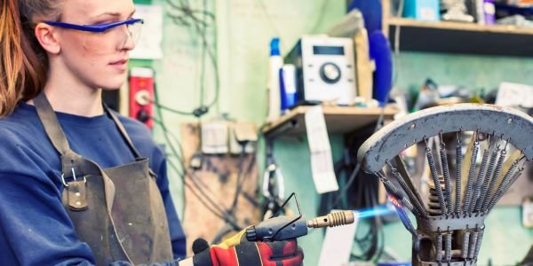
| Torch brazing | Oxy-acetylene, oxy-propane or air-fuel flame, usually by hand | Repairs, site work, HVAC copper lines, small batches | Quality depends on the operator; flux needed except BCuP on copper |
| Furnace brazing | Parts with pre-placed filler go through a batch or continuous belt furnace, in a protective gas | High volume, many joints per part brazed at once | Whole part is heated, so it may soften heat-treated metal |
| Vacuum brazing | Furnace under vacuum, no flux | Stainless steel, nickel superalloys, titanium, aerospace and turbine parts, plate heat exchangers | Expensive equipment; long cycles |
| Induction brazing | A water-cooled copper coil induces eddy currents in the joint area | Repeat production of shafts, fittings, carbide tips; heats in seconds | A coil must be designed for each joint shape |
| Dip brazing | Assembly dipped in a bath of molten salt (flux) or molten filler | Complex aluminium assemblies, small parts in bulk | Salt residues must be washed out thoroughly |
| Resistance brazing | Current passed through the joint between electrodes | Electrical contacts, small copper conductors, wire ends | Only small, conductive joints |
Brazing filler metals (AWS A5.8 classes)
Brazing filler metals are classified in AWS A5.8, “Specification for Filler Metals for Brazing and Braze Welding”. The prefix B means brazing filler and the letters after it are the main elements; an R in front, as in RBCuZn, marks a filler also sold as rod for braze welding, and a V, as in BVAg, marks a grade made for vacuum service. The main families:
| AWS class | Main elements | Approx. melting range | Typical use |
|---|---|---|---|
| BAg (silver) | Silver, copper, zinc, often tin or nickel | About 600 to 900 °C depending on grade | Steel, stainless, copper, brass and carbide, including dissimilar pairs; flux needed |
| BCuP (copper-phosphorus) | Copper, phosphorus, some grades with silver | BCuP-2: 710 to 793 °C | Copper to copper without flux; copper to brass with flux. Not on steel or nickel |
| BCu (copper) | At least 99% copper | Melts at about 1,085 °C | Furnace brazing of steel in hydrogen or vacuum |
| RBCuZn (copper-zinc, brass) | Copper and zinc, about 60/40 | About 865 to 900 °C | Steel, cast iron and copper by torch; braze welding |
| BAlSi (aluminium-silicon) | Aluminium with about 7 to 12% silicon | BAlSi-4: 575 to 585 °C | Aluminium heat exchangers, often as cladding on the sheet |
| BNi (nickel) | Nickel with chromium, boron, silicon or phosphorus | About 890 to 1,040 °C for common grades; brazed hotter | Stainless steel and superalloys for high-temperature, corrosive service; vacuum furnace |
A5.8 also covers gold (BAu), magnesium (BMg), cobalt (BCo), titanium and palladium-bearing fillers, used in aerospace, electronics and vacuum devices.
Two practical points on silver fillers. First, more silver usually means a lower flow temperature, better fluidity and a higher price. Second, some older grades such as BAg-1 contain about 24% cadmium, whose fumes are highly toxic. Cadmium-free grades such as BAg-7 or BAg-24 are the normal choice now, and are the only sensible choice for food, drinking water and medical equipment.
To choose a filler, start from the base metals (the table above), then check that the service temperature stays well below the filler’s solidus, that the parts can take the brazing heat, and that the filler resists the fluid in service. Silver content drives the price, so use the least silver that does the job.
Step-by-step brazing procedure
For a torch-brazed joint with flux:
- Fit the parts to the right clearance and check the overlap.
- Clean both surfaces: degrease, then remove oxide.
- Apply flux to both faces and to the filler rod, unless you are using BCuP on copper or a protective atmosphere.
- Assemble and fixture so the parts cannot move while the filler is liquid.
- Heat the joint evenly, with a broad flame and more heat on the heavier part. The flux goes clear and fluid as the metal nears brazing temperature.
- Feed the filler to the edge of the joint. The hot parts melt it and capillary action draws it through, towards the hotter side. Do not melt the rod in the flame and drip it on.
- Cool without disturbing the joint until the filler has solidified.
- Remove flux residue, usually by soaking or scrubbing in hot water once the part has cooled.
- Inspect the joint.
Student tip: in a lab or viva, “heat the work, not the rod” is the one sentence examiners want to hear about brazing technique.

Brazing defects and inspection
| Defect | Usual cause |
|---|---|
| Lack of fill, voids | Gap too wide or too tight, uneven heating, dirty surface |
| Flux entrapment | Too much flux, or a gap too narrow for flux to escape |
| Filler did not flow, balled up | Oxide or grease, exhausted flux, joint too cold |
| Porosity | Overheating, which boils zinc out of silver and brass fillers; gas from dirty parts |
| Erosion of base metal | Too high a temperature or too long a hold, so the filler dissolves the parent metal |
| Cracks | Thermal stress between dissimilar metals, fast cooling, phosphide embrittlement from BCuP on steel |
| Corrosion after brazing | Flux residue left on the part |
Inspection starts with a visual check for a continuous fillet on both sides. Pressure joints get a leak test (soap bubble, pressure decay, or helium for refrigeration and vacuum work), and ultrasonic or radiographic testing can reveal internal voids. To qualify a procedure, sample joints are sectioned or peeled apart to see how much of the area actually bonded.
Advantages and limitations of brazing
| Advantages | Limitations |
|---|---|
| Base metal does not melt, so distortion and metallurgical damage are low | Joint strength depends on overlap area; lap joints add material and weight |
| Joins dissimilar metals (copper to steel, carbide to steel) and even metals to ceramics | Service temperature is limited by the filler’s melting range |
| Thin walls and delicate parts can be joined | Needs close, controlled clearances and clean surfaces |
| Leak-tight, conductive joints with a neat fillet that needs little finishing | Flux residue is corrosive and must be removed |
| A furnace can make hundreds of joints in one cycle | Silver and nickel fillers are expensive |
Compared with welding, brazing gives up some strength and high-temperature capability in return for low distortion and the ability to join unlike metals. TIG welding is the better choice for thick, load-bearing butt joints.
Applications of brazing
- Air conditioning and refrigeration: copper suction and discharge lines, evaporator and condenser coils, and compressor connections in HVAC systems. BCuP is used for copper to copper, and silver filler where copper meets steel or brass. These joints carry refrigerant under pressure round the vapour compression cycle.
- Heat exchangers: aluminium car radiators and condensers (CAB furnace); stainless plate heat exchangers brazed with copper or nickel.
- Cutting tools: carbide tips on lathe tools, saw teeth and mining bits, silver-brazed to steel shanks, often with a copper shim to absorb thermal stress.
- Aerospace and power: nickel superalloy turbine parts and seals, vacuum brazed with BNi.
- Plumbing, gas and electrical: copper gas and medical gas pipework, busbars, motor windings and switchgear contacts.
- Bicycles and jewellery: lugged steel frames, gold and silver jewellery.
A related process, braze welding, uses a brass (RBCuZn) filler deposited in a groove or fillet like a weld, without relying on capillary flow. It is used to repair cast iron and to join galvanised steel.
References
- AWS A5.8M/A5.8, Specification for Filler Metals for Brazing and Braze Welding, American Welding Society (AWS).
- M. Way, J. Willingham and R. Goodall, “Brazing filler metals”, International Materials Reviews, 2020: review of brazing filler metals.
- TWI – Welding Job Knowledge, articles on brazing practice.
FAQs
What is brazing in engineering?
Brazing is a thermal joining process in which a filler metal with a liquidus above 450 °C, but below the melting point of the base metals, is melted and drawn into a close-fitting joint by capillary action.
What filler metal is used for brazing?
It depends on the base metals: copper-phosphorus (BCuP) for copper to copper without flux, silver alloys (BAg) for steel, stainless, brass and carbide, pure copper (BCu) for furnace brazing of steel, aluminium-silicon (BAlSi) for aluminium, and nickel alloys (BNi) for hot, corrosive service.
What is the ideal joint clearance for brazing?
For flux brazing with silver filler, about 0.05 to 0.13 mm per side, with the strongest joints near 0.04 mm. Flux-free furnace brazing can use tighter gaps. With dissimilar metals, check the gap at brazing temperature.
Why is flux used in brazing?
Flux dissolves the thin oxide film on the hot metal and stops new oxide forming, so the molten filler can wet the surface and flow into the joint. It is not needed with copper-phosphorus filler on copper, or in vacuum and protective-atmosphere furnaces.
What are the main applications of brazing?
AC and refrigeration copper lines, aluminium radiators and heat exchangers, carbide-tipped tools, turbine parts, gas pipework, electrical busbars and windings, bicycle frames and jewellery.
Related Topics on EngineeringHulk
Keep reading
Cold Welding: How It Works, Process, Metals and Applications
How does cold welding work? Pressure breaks the oxide film so clean metal atoms bond at room temperature. Process, metals, space and wiring uses, limits.
Casting Process: Steps, Types, Defects and Applications
Casting process explained: foundry steps from pattern and mould to pouring and fettling, casting types compared, defects with remedies, and worked maths.
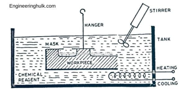
Chemical Machining (CHM): Process Steps, Etchants, Etch Factor and Applications
Chemical machining explained: chemical milling and photoetching, masking and etching steps, etchants by material, etch factor, tolerances and applications.
Knurling: Process, Types, Patterns, Diameter Calculation and Applications
Knurling presses straight, diagonal or diamond ridges onto a turned part by displacing metal. Tool types, patterns, IS 3403 diameter sizing and defects.
Welding Aluminium: Techniques, Challenges, Filler Choice and Applications
Welding aluminium explained: oxide layer, porosity, hot cracking and soft HAZ, AC TIG and spool-gun MIG, 4043 vs 5356 filler, prep and a worked example.
Metal Hemming: Types, Process, Applications and Benefits
Metal hemming folds a sheet edge back on itself. Open, closed, teardrop and rope hems, press vs roller hemming for car panels, design rules and defects.