A vernier bevel protractor is a precision angle-measuring instrument that reads any angle from 0° to 360° to 5 minutes of arc (5′, or 1/12 of a degree). A stock is held against one face of the job and an adjustable blade against the other; the angle between them is read on a degree scale on a rotating disc, and a vernier plate splits each degree into twelve parts. It is the standard angle tool in machine shops, toolrooms and B.Tech metrology labs.
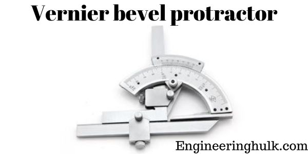
Parts of a vernier bevel protractor
| Part | What it does |
|---|---|
| Stock (base) | The fixed reference arm, with a flat, lapped working edge that rests on one face of the job or on a surface plate. |
| Main scale (body) | A circular scale fixed to the stock, graduated in degrees in four quadrants: 0-90-0-90. |
| Turret disc with vernier plate | A disc that rotates inside the body and carries the vernier scale, 12 divisions on each side of its zero. The blade is clamped to this disc, so the vernier turns with the blade. |
| Blade | A hardened steel straightedge, commonly 150 mm and 300 mm long, often with 30°, 45° and 60° bevelled ends. It slides along its own length and is locked by a blade clamp. |
| Acute-angle attachment | A small bar fixed to the stock that gives an extra working face, so angles under 90° can be measured on small or awkward parts. |
| Disc locking nut | Locks the disc so the reading stays fixed while the tool is lifted off the job. |
| Blade clamp nut | Locks the blade at the required extension. |
| Fine-adjustment knob and magnifier | Found on many models; the knob makes small final movements, the lens helps pick the coinciding vernier line. |
Least count in one line
The least count is 5 minutes: one main-scale division (1°) divided by 12 vernier divisions. The derivation, the 12-over-23 construction and worked reading examples are in our separate article on the least count of a vernier bevel protractor.
How a vernier bevel protractor works
The blade and the stock form the two arms of the angle. When you swing the blade, the disc turns by the same angle relative to the stock, and the vernier zero moves along the fixed degree scale. Whole degrees are read where the vernier zero sits on the main scale; the extra minutes come from whichever vernier line lines up exactly with a main-scale line, multiplied by 5′. The vernier is read on the same side of zero as the main scale is counting.
Setting up and measuring an angle, step by step
- Clean the stock edge, blade and job faces. A chip or burr under the stock tilts the whole measurement.
- Check zero: close the blade flat against the stock edge. The vernier zero should line up with the main-scale zero.
- Choose the blade length. Use the shortest blade that spans the face, as a long overhanging blade flexes more easily.
- Rest the stock firmly on the reference face of the job (or on a surface plate when the job sits on it).
- Loosen the disc nut, swing the blade until it touches the second face along its full length, and hold it up to the light. No light should show between blade and face.
- Tighten the disc locking nut, lift the tool away and read it square-on in good light.
Acute angles and obtuse angles (the supplement reading)
The main scale only runs 0-90° in each quadrant, so the dial always shows an angle between 0° and 90°. You decide from the set-up whether the angle on the job is that reading or its supplement.
- Acute angle (under 90°): the angle between blade and stock on the job is the reading itself. For small or narrow jobs, fit the acute-angle attachment and use it as the reference face.
- Obtuse angle (over 90°): the job angle is 180° minus the reading. Example: the dial reads 52°20′, and the job face opens wider than a right angle, so the angle is 180° – 52°20′ = 127°40′.
Tip: before you trust the number, glance at the job. If the angle clearly looks wider than a square corner and your answer is below 90°, you have forgotten to take the supplement.
What is the accuracy of a vernier bevel protractor?
Resolution and accuracy are not the same thing. The vernier lets you read to 5′, but the measurement is only as good as the instrument and the set-up. Manufacturers typically state an accuracy of about ±5′ for a good universal bevel protractor (Mitutoyo, for example, lists ±5′ for its 5′-graduation models). In practice that means you should not report results finer than about 5′ from this tool. In India, bevel protractors are specified in IS 4239:2023, Bevel Protractors – Specification, issued by the Bureau of Indian Standards; it replaced the older IS 4239:1970, which was titled “Mechanical Bevel Protractors”.
Sources of error
- Parallax: reading the vernier from an angle makes the wrong line appear to coincide. Look square-on, use the magnifier and lock the disc first.
- Zero error: if the vernier zero does not match the main-scale zero with the blade closed on the stock, every reading carries that offset. Note it and correct the reading, or have the tool reset.
- Blade flatness and straightness: a bent, nicked or worn blade rocks on the job face and gives an angle that changes with where you press.
- Poor seating: dirt, burrs or a stock that is not held fully down on the reference face. This is the most common source of error in a lab.
- Looseness: worn pivots or a loose blade clamp let the blade move after it is set.
- Temperature: a uniform temperature change does not alter an angle, but a blade warmed on one side by the hand can bow slightly, and a hot job straight off the machine will not measure the same when cold. Let both settle to room temperature for close work.
- Reading the wrong side of the vernier or forgetting the supplement for obtuse angles, both covered above.
Care and calibration
- Wipe the blade and stock after use and apply a thin film of oil against rust. Store the tool in its box with the blade removed or retracted.
- Never use the blade as a scraper, lever or marking tool. Do not drop it: one knock can bend the blade or shift the zero.
- Check zero and blade straightness before a batch of measurements. A quick straightness check is to hold the blade against a straightedge or surface plate and look for light.
- Calibrate at fixed intervals (many labs use 12 months, depending on use) against angle gauges or a sine bar and slip gauges, at several angles across the range and in more than one quadrant. Keep the calibration record with the tool.
Types of bevel protractor
- Mechanical vernier bevel protractor: the classic type described here, reading to 5′.
- Dial bevel protractor: a pointer on a small dial replaces the vernier, which makes readings quicker and removes the need to pick the coinciding line.
- Digital (electronic) protractor: an encoder and LCD display. Typical figures are 1′ (0.01°) resolution with an accuracy of about ±2′ (for example, Mitutoyo’s 187-551 is listed at ±0.03°). They can zero anywhere, which makes comparing two angles easy.
- Universal bevel protractor: the same instrument with a full set of blades and the acute-angle attachment, able to measure through the whole 360°. Many workshop “vernier bevel protractors” are universal models.
- Optical bevel protractor: reads through an eyepiece on a finely divided glass circle, for toolroom work finer than 5′.
Bevel protractor vs simple protractor vs sine bar
| Point | Simple protractor | Vernier bevel protractor | Sine bar with slip gauges |
|---|---|---|---|
| Reads to | 1° | 5′ | A few seconds of arc when set carefully |
| How the angle is found | Direct reading on a semicircle | Direct reading with vernier | Calculated: sin θ = h / L |
| Range | 0-180° | 0-360° | Best below about 45°; accuracy falls as the angle rises |
| Extra equipment | None | None | Surface plate, slip gauges, dial indicator |
| Speed | Very quick | Quick | Slow |
| Typical use | Drawing, rough layout | Workshop checking and setting | Inspection and calibration of angles, tapers and gauges |
Applications of a vernier bevel protractor
- Checking chamfers, bevels and V-grooves on turned and milled parts.
- Setting the swivel of a vice, milling head, compound rest on a lathe, or a saw fence to a required angle.
- Checking the included angles of cutting tools and the point angle of drills (118° is the common general-purpose value).
- Inspecting dovetails, die and mould faces, jigs and fixtures.
- Marking out angles on a surface plate with the blade as a guide.
- Weld-edge preparation and fabrication, where the bevel angle on a plate edge must be checked before welding.
- Metrology practicals in diploma and B.Tech courses, where it is usually the first precision angle instrument students meet, alongside the vernier caliper for lengths.
FAQs
What is a vernier bevel protractor used for?
It measures and sets angles between two faces of a job to 5 minutes of arc. Typical uses are checking chamfers, bevels, dovetails and tool angles, and setting machine vices or heads to an angle.
What is the accuracy of a vernier bevel protractor?
It reads to 5′ (1/12 of a degree), and good instruments are typically specified to about ±5′. Actual accuracy depends on the set-up: parallax, zero error, dirt and a bent blade can each add error.
How do you read a vernier protractor for an obtuse angle?
Read the dial normally, then subtract the reading from 180°. A reading of 52°20′ on an obtuse set-up means the job angle is 127°40′.
What is the difference between a vernier protractor and a universal bevel protractor?
Very little. A universal bevel protractor is a vernier (or digital) bevel protractor supplied with interchangeable blades and an acute-angle attachment so it can measure through a full 360°.
Which Indian standard covers bevel protractors?
IS 4239:2023, Bevel Protractors – Specification, from the Bureau of Indian Standards. It replaced IS 4239:1970, Mechanical Bevel Protractors.