 EngineeringHulk
- Home
- Blog
- Manufacturing Engineering
- Knurling: Process, Types, Patterns, Diameter Calculation and Applications
Knurling: Process, Types, Patterns, Diameter Calculation and Applications
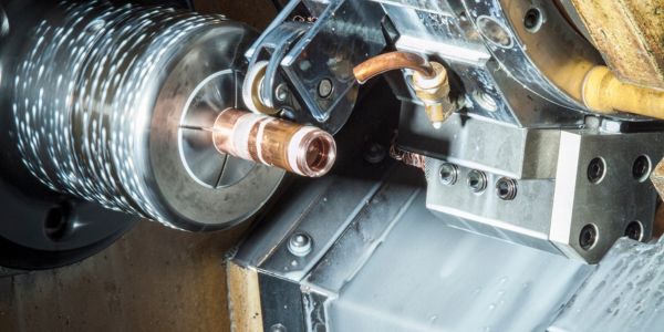
On this page
- Is knurling a cutting operation?
- Why knurling is done
- Knurling tools
- Knurling patterns
- Knurling standards
- The knurling diameter calculation
- Speed, feed and coolant
- Knurling procedure on a lathe, step by step
- Common knurling defects and their fixes
- Materials: what knurls well and what does not
- Applications of knurling
- References
- FAQs
- Related Topics on EngineeringHulk
Knurling is a cold-forming operation, normally done on a lathe, in which a hardened wheel is pressed into a rotating workpiece and rolls a pattern of straight, diagonal or diamond ridges into the surface. It displaces metal rather than removing it, so no chip is produced and the diameter grows instead of shrinking. The one exception is cut knurling, a separate process that genuinely machines the pattern out of the surface and is described further down.
Understanding that difference matters, because the standard forming case is where almost every knurling mistake starts: the blank has to be turned undersize and the circumference has to divide into a whole number of teeth, or the pattern comes out doubled and blurred.

Is knurling a cutting operation?
No. Form knurling, which is what the word means when it is used on its own, is a chipless cold-forming process. The knurl wheel carries a hardened, hobbed tooth profile. Pressed hard against the turning workpiece, it rolls without slipping and the teeth sink into the surface. The metal under each tooth has to go somewhere, so it flows sideways and upwards into the gaps between the teeth, which is what forms the raised ridges.
Three consequences follow directly, and all three are testable:
- The diameter increases. Metal is pushed out, not taken away. A knurled surface finishes larger than the blank it started from, typically by a third to two thirds of the knurl pitch.
- The surface work hardens. Cold plastic flow raises the hardness of the ridges, which is why a knurled grip wears well.
- The radial force is high. A single-wheel knurl pushing into steel can put a load of several kilonewtons straight into the workpiece and the cross slide, which is why slender parts bend and why the lathe has to be in reasonable condition.
Cut knurling is the genuine exception. There the wheel has sharp, relieved cutting edges set at an angle to the work, and it removes a fine chip to produce the pattern instead of squeezing it out.
Why knurling is done
- Grip. The main reason. A knurled thumbscrew, micrometer thimble or valve knob can be turned with oily fingers or gloves. The ridges break through the film of oil that makes a smooth surface slip.
- Appearance. A knurled band reads as a “turn this part” cue and hides small surface defects on a hand-finished component.
- A light interference fit. A knurled shaft pressed into a plain bore, or a knurled brass insert pressed or heat-staked into a plastic moulding, grips because the ridges bite into the softer material and resist both pull-out and rotation.
- Increasing a diameter slightly. Because form knurling raises the diameter in a predictable way, it is sometimes used to rescue a shaft that has been turned a few hundredths undersize for its bearing seat. It works, but treat it as a repair, not as a design method: the contact is on ridge crests only, so the bearing seat loses most of its support area.
- Keying for an overmould. A knurled insert moulded into plastic or rubber will not spin in its housing.
Knurling tools
| Tool type | How it works | Where it is used |
|---|---|---|
| Knuckle or bump type | One or two wheels in a fixed head, carried on the tool post and fed straight in with the cross slide. All the forming load goes into the workpiece on one side. | The common workshop knurl. Cheap and simple, but it bends slender work and loads the lathe heavily. |
| Scissor or clamp type (straddle knurl) | Two wheels on pivoted arms that close on the work from opposite sides, tightened by a screw. The two radial forces cancel each other out. | The correct choice for long, thin or unsupported parts, and the one that lets you reach full depth in a single pass. Standard on capstan and turret work. |
| Cut knurling tool | A single wheel with sharp, relieved teeth held in a holder that sets it at a defined angle to the work axis, so it machines the pattern out. | CNC turning, thin-walled tube, soft and gummy materials, and any job where the finished diameter has to stay under control. |
| End or face knurling tool | A wheel fed axially against a flat face rather than radially against a diameter. | Knurled washers, clutch faces and anti-rotation faces. |
Form knurling vs cut knurling
| Point | Form knurling | Cut knurling |
|---|---|---|
| Mechanism | Cold plastic displacement, no chip | Metal removal, produces a fine chip |
| Effect on diameter | Grows by about 0.33P to 0.67P depending on pattern | Very little change; the tool cuts to a set diameter |
| Radial force on the work | Very high | Low, comparable to a light turning cut |
| Thin-walled tube | Collapses or goes out of round | Handles it, because the wall is not being squeezed |
| Soft materials (aluminium, copper, plastics) | Smears and flakes easily | Clean, sharp pattern |
| Pattern quality and repeatability | Depends on correct blank sizing; can double-track | Sharper crests, repeatable part to part |
| Suits CNC? | Poorly, high loads and an uncertain finished size | Yes, this is the reason it exists |
| Tool cost | Low | Higher; the holder and wheels are precision items |
Cut knurling suits CNC for two practical reasons. First, the finished diameter is set by the tool position and not by how far the metal happens to flow, so the size is predictable and the machine can hold a tolerance on it. Second, the load is a fraction of that in form knurling, so a bar sticking out of the collet is not pushed off centre and the spindle bearings are not hammered. It can also knurl right up to a shoulder and produce a blind knurl, which a bump knurl cannot do cleanly.
Knurling patterns
The Indian standard IS 3403:1981, Dimensions for knurls (reaffirmed 2002, drawn from DIN 82-1973) names seven patterns with a three-letter code. The letter R separates a knurl from a knurling wheel, the second letter gives the basic type and the third gives the direction or form.
| Code | Pattern | Description |
|---|---|---|
| RAA | Straight knurl | Grooves parallel to the axis. Best grip for a straight pull or push, and the easiest to size because the pitch is measured directly around the circumference. |
| RBL | Left-hand diagonal | Single helix, teeth at 30 degrees to the axis. |
| RBR | Right-hand diagonal | The same at the opposite hand. Diagonals give a good grip against twisting and look neater than a straight knurl. |
| RGE | Diamond, points raised | Left-hand and right-hand helices superimposed, leaving raised pyramids. This is the “male” diamond most people picture when they hear the word knurling. |
| RGV | Diamond, points indented | The same crossing pattern with the diamonds sunk instead of raised, so the original surface stays as the high point. |
| RKE / RKV | Cross-knurl, raised / indented | Grooves crossing at 90 degrees rather than as opposed helices. |
A convex knurl is the other pattern you will meet in tool catalogues, though it is not one of the IS 3403 forms. Its teeth have rounded rather than sharply pointed crests, giving a bead-like surface that grips without being sharp on the hand and with no fine crevices to trap dirt. It is used on medical and food equipment handles and on grips that are held for a long time.
How the diamond pattern is actually produced
Two ways, and both are in IS 3403’s own manufacturing appendix:
- Two wheels of opposite hand. The knurling head carries a left-hand and a right-hand wheel of the same pitch, one above the other. Each wheel rolls its own helix into the surface and the two helices cross, so the metal left standing between them is a field of pyramids. This is the usual arrangement on a bump or scissor knurl.
- One wheel that already carries the crossed form. A single GE or GV wheel has the diamond hobbed into it, so it impresses the finished pattern in one go. Note the inversion: a wheel with raised points produces an indented knurl on the work, and a wheel with indented points produces a raised knurl, because the wheel is the negative of the part.
A third route exists for the diagonals: an ordinary straight AA wheel swivelled 30 degrees in the holder will roll a left- or right-hand diagonal, and a pair of them swivelled the same way will produce a diamond.
Knurling standards
| Standard | What it covers | Key content |
|---|---|---|
| ISO 13444:2012 | Technical product documentation: dimensioning and indication of knurling | How to put a knurl on a drawing. Profile angle 90 degrees; pitch chosen from 0.4, 0.5, 0.6, 0.8, 1.0, 1.2 and 1.6 mm; teeth parallel to the axis or at a 30 degree helix; the diameter shown on the drawing is d1, the outside diameter of the finished knurl. |
| IS 3403:1981 | Dimensions for knurls (Indian Standard, reaffirmed 2002) | The seven pattern types, profile angle 90 degrees, pitches 0.5 to 1.6 mm, and the formulae for the initial workpiece diameter. Designation example: Knurl RKV 08 IS 3403. |
| IS 6776:1980 | Specification for knurling wheels | The tools themselves, matched to the knurl types of IS 3403. |
| DIN 82 (1973) | Knurls (German standard) | The parent document for both the RAA/RBL/RBR/RGE/RGV/RKE/RKV codes and the initial-diameter formulae. IS 3403 states openly that it was prepared with assistance from DIN 82. |
One useful detail from the IS 3403 explanatory note: the 2 mm pitch was dropped in the 1981 revision because it was scarcely used, and the standard deliberately makes no attempt to tie pitch to workpiece diameter, having found that earlier recommendations did not hold across all applications. The diameter rule in the next section is therefore shop practice, not a code requirement.
The knurling diameter calculation
This is the part that decides whether the job comes out right, and it has two separate requirements that have to be satisfied together.
Requirement 1: the blank must be undersize, because the diameter grows
IS 3403 defines d1 as the nominal diameter, meaning the outside diameter of the finished knurl, and d2 as the initial diameter of the workpiece before knurling. For a 90 degree profile angle it gives these formulae, where P is the pitch:
| Knurl type | Pattern | Initial diameter d2 |
|---|---|---|
| RAA, RBL, RBR | Straight and diagonal | d1 – 0.5 P |
| RGE, RKE | Diamond and cross, points raised | d1 – 0.67 P |
| RGV, RKV | Diamond and cross, points indented | d1 – 0.33 P |
So the common workshop advice to “turn it about a third of the pitch undersize” is the figure for the indented patterns. A straight knurl needs half the pitch and a raised diamond needs two thirds, because a raised diamond displaces the most metal of the three. The standard adds a warning worth repeating: these factors ignore the rounding of the groove crests and the properties of the material, so they are reference values to be trimmed by trial on the first piece.
Requirement 2: the circumference must hold a whole number of teeth
The wheel rolls on the work without slipping. After one full revolution of the workpiece the teeth have to drop back into the impressions they made at the start. They only do that if the circumference contains an exact whole number of tooth spacings:
n = πd2 / pc must be a whole number
where pc is the tooth spacing measured around the circumference and n is the number of teeth rolled into the surface. If n comes out at, say, 76.5, the wheel arrives half a tooth out of step on the second revolution, starts a second set of impressions between the first, and you get the doubled, blurred pattern called double tracking.
For a straight RAA knurl the grooves run along the axis, so the standard pitch P is the circumferential spacing and pc = P. For the 30 degree helical types (RBL, RBR, RGE, RGV) the pitch is measured perpendicular to the teeth, so the spacing seen around the circumference is larger:
pc = P / cos 30° = 1.155 P
Use that larger value in the tracking check for any diagonal or diamond pattern.
Worked example 1: straight knurl, 20 mm finished diameter
Problem. A knob is to be finished at 20 mm diameter with a straight RAA knurl of pitch P = 0.8 mm. Find the diameter to turn the blank to.
- Initial diameter from IS 3403. d2 = d1 – 0.5P = 20 – (0.5 x 0.8) = 20 – 0.40 = 19.60 mm
- Tracking check. The pattern is straight, so pc = P = 0.8 mm.
n = π x 19.60 / 0.8 = 61.575 / 0.8 = 76.97 teeth, which is not a whole number. - Round to the nearest whole tooth and work back. Take n = 77.
d2 = n pc / π = (77 x 0.8) / π = 61.60 / 3.1416 = 19.61 mm - Result. Turn the blank to 19.61 mm. That is only 0.008 mm off the IS 3403 value, well inside an ordinary turning tolerance, so the finished knurl still lands at about 20.0 mm.
Worked example 2: when the two requirements disagree
Problem. A 12 mm finished diameter with a straight RAA knurl of pitch P = 0.6 mm.
- d2 from the formula = 12 – (0.5 x 0.6) = 11.70 mm
- n = π x 11.70 / 0.6 = 36.757 / 0.6 = 61.26 teeth. Not whole, and this time not close either.
- The two candidates are:
- n = 61: d2 = (61 x 0.6) / π = 36.60 / 3.1416 = 11.65 mm, which is 0.05 mm below the formula value.
- n = 62: d2 = (62 x 0.6) / π = 37.20 / 3.1416 = 11.84 mm, which is 0.14 mm above it.
- Take n = 61 and turn to 11.65 mm. The finished knurl will come out around 11.95 mm, a little under the nominal 12 mm. Erring undersize is the safer error: too much material and the crests tear and flake instead of forming cleanly.
Worked example 3: diamond knurl, where the helix has to be allowed for
Problem. A 25 mm finished diameter with a raised diamond RGE knurl, pitch P = 1.0 mm.
- d2 = d1 – 0.67P = 25 – 0.67 = 24.33 mm
- The teeth sit at a 30 degree helix, so pc = 1.0 / cos 30° = 1.0 / 0.8660 = 1.1547 mm
- n = π x 24.33 / 1.1547 = 76.437 / 1.1547 = 66.20 teeth
- Round to n = 66: d2 = (66 x 1.1547) / π = 76.210 / 3.1416 = 24.26 mm
- Turn the blank to 24.26 mm, 0.07 mm below the IS 3403 figure.
Two things make this less exact than it looks. The displaced metal does not all end up in the crests, so the real finished diameter has to be measured on the first piece and the blank adjusted; and the crests round over, which is exactly the effect the standard warns its formulae ignore. Do the arithmetic, then prove it on one part before running the batch.
Speed, feed and coolant
| Parameter | Form knurling | Notes |
|---|---|---|
| Cutting speed | Roughly a quarter to a third of the speed you would use to turn the same material; about 10 to 25 m/min in steel, a little more in brass and aluminium | Slow speed keeps the wheel and the work cool and gives the metal time to flow. Cut knurling runs at close to normal turning speed. |
| Spindle speed | N = 1000V / (πd). A 20 mm blank at 15 m/min needs N = 15000 / (π x 20) = 15000 / 62.83 = about 240 rev/min | Work it out rather than guessing; the same surface speed on a 60 mm part is only 80 rev/min. |
| Feed | Up to about half the knurl pitch per revolution (0.5 mm/rev for a 1 mm pitch), and often less | Too slow a feed keeps re-rolling the same ridges and causes flaking. |
| Depth per pass | Scissor or clamp knurl: full depth in one pass. Bump knurl: two or three passes, roughly 0.1 to 0.2 mm of infeed per pass | Stop the moment the crests come to a point. Going further flattens and tears them. |
| Coolant | Flood, generously. Cutting oil for steel, soluble emulsion for brass and aluminium | This is not optional. Coolant lubricates the wheel pivot pins, cools the work and, most importantly, flushes the displaced flakes out of the wheel teeth before they are rolled back into the pattern. |
Knurling procedure on a lathe, step by step
- Hold the work short. Chuck it with minimum overhang and support the free end with a centre or a steady rest. Form knurling loads are high enough to bow an unsupported bar.
- Turn the blank to the calculated d2. Use the IS 3403 formula, then adjust to a whole number of teeth as in the examples above. Keep the surface round; cut knurling in particular wants out-of-roundness under about 0.03 mm.
- Mark the length of the knurl with a light scribe or a parting tool nick, so you know where to stop.
- Set the tool on centre height and square to the axis. Off centre height gives a shallow pattern on one flank; out of square gives a knurl that is deeper at one end.
- Select the speed from the calculation, engage a fine power feed, and turn the coolant on before the wheel touches.
- Start about half the wheel width onto the end of the work and plunge in firmly enough to raise a visible pattern on the very first revolution. A timid start is the commonest cause of double tracking.
- Check the pattern immediately. Stop the machine and look. Sharp, single, clearly formed diamonds means it is tracking. A doubled or fuzzy pattern means back off, adjust the diameter, and start again on fresh metal. You cannot correct double tracking by pushing harder.
- Engage the feed and traverse the full length in one direction, then feed a little deeper and traverse back if a second pass is needed. Do not stop the feed mid-knurl.
- Stop when the crests are just sharp. Measure over the crests if the drawing calls a finished diameter.
- Break the edges and clean up. Deburr both ends of the knurled band with a file or a light chamfer, then brush the flakes off the wheels before the next part.
Common knurling defects and their fixes
| Defect | Cause | Fix |
|---|---|---|
| Double tracking (a doubled, blurred pattern with twice as many shallow ridges) | The circumference is not a whole multiple of the circumferential pitch, or the wheel did not bite hard enough on the first revolution and started a second set of tracks | Recalculate d2 = n pc / π and re-turn the blank; plunge firmly at the start; check the tool is on centre height and square |
| Flaking or tearing of the crests | Too much metal being displaced (blank oversize for the pitch), too many passes over the same ridges, flakes packed into the wheel teeth, or a material that is soft and gummy | Reduce the blank diameter, use a coarser pitch, flood with coolant, cut the number of passes, brush the wheels between parts; switch to cut knurling for soft materials |
| Pattern too shallow, poor grip | Not enough infeed, a worn or blunt wheel, or a slender part springing away from a single-wheel knurl | Increase the infeed in small steps, replace the wheel, or change to a scissor knurl so the forces balance |
| Flats on the workpiece, wheel skidding | The wheel pivot pin has seized, so the wheel drags instead of rolling | Oil the pins before every job; replace worn pins and bushes |
| Knurl deeper at one end | Tool not parallel to the work axis, or the tailstock is set over | Square the tool to the axis and check the tailstock alignment |
| Bell-mouthed or ragged ends | The wheel ran off the end of the work, or the feed was stopped and restarted part way | Start half a wheel width on, traverse in one continuous pass, and chamfer both ends afterwards |
| Work bent or pushed off centre | Radial load from a bump knurl on a long, thin or unsupported part | Support with a centre or steady rest, or use a scissor or cut knurling tool |
| Tube gone out of round | Form knurling a thin wall, which simply collapses under the radial load | Cut knurling, or an internal mandrel to support the bore |
Materials: what knurls well and what does not
Knurls well. Low carbon and free-cutting steels, mild steel, brass, bronze, copper, most aluminium alloys and engineering plastics such as acetal and nylon. The requirement is ductility: the metal must flow cold without cracking. Free-cutting brass and leaded steels give the sharpest crests with the least effort.
Knurls badly or not at all.
- Hardened steel above roughly 30 to 35 HRC. The wheel cannot indent it; the wheel teeth flatten instead. Knurl before hardening.
- Grey cast iron. The graphite flakes act as internal cracks, so the surface crumbles instead of flowing and the pattern comes out broken.
- Thin-walled tube. The wall buckles under a form knurl. Use cut knurling or support the bore.
- Very soft, gummy metals such as pure aluminium or lead. They smear and pick up on the wheel rather than holding a crisp crest.
- Brittle plastics such as acrylic and polystyrene, which craze and crack under the local pressure.
Applications of knurling
- Measuring instruments. Micrometer thimbles and ratchets, vernier caliper thumbwheels, dial gauge bezels and microscope focus knobs.
- Hand-operated fasteners. Thumb screws, knurled nuts, captive screws, setscrews and adjusting collars that are meant to be turned without a tool.
- Tool and equipment handles. Screwdriver ferrules, tap wrenches, valve handwheels, torch and pen barrels.
- Medical and laboratory equipment. Surgical instrument grips and laboratory fittings, usually with a fine or convex pattern that is easy to clean.
- Press-fit inserts. Knurled brass inserts pressed or heat-staked into plastic mouldings so a machine screw can be used; the knurl is what stops the insert spinning.
- Assemblies and fabricated parts. Knurled studs and pins pressed into sheet metal fabrication work to provide a threaded or locating feature without welding.
- Repair work. Raising a slightly undersize shaft back to a working size, accepted as a field fix rather than as good design.
References
- Bureau of Indian Standards, IS 3403:1981 (reaffirmed 2002), Dimensions for Knurls (first revision).
- Bureau of Indian Standards, IS 6776:1980, Specification for Knurling Wheels (first revision).
- ISO 13444:2012, Technical Product Documentation (TPD) – Dimensioning and Indication of Knurling.
- DIN 82:1973, Knurls, Deutsches Institut fuer Normung.
- NPTEL – Machine Tools lecture series, IIT.
- AICTE Model Curriculum – Manufacturing Technology.
FAQs
What is knurling and what is it used for?
Knurling is a cold-forming operation on a lathe in which a hardened wheel is pressed into a rotating workpiece and rolls a pattern of straight, diagonal or diamond ridges into the surface. It is used mainly to give a non-slip grip on knobs, thumbscrews, micrometer thimbles and tool handles, and also for appearance, for a light interference fit and to raise a diameter slightly.
Is knurling a cutting or a forming process?
Form knurling, the ordinary lathe operation, is a forming process. No chip is produced; the wheel displaces metal sideways into ridges, so the diameter grows and the surface work hardens. Cut knurling is the exception: it uses a sharp, relieved wheel set at an angle to the work and genuinely removes material, which is why it suits CNC turning, thin-walled tube and soft materials.
How do you calculate the workpiece diameter before knurling?
Two steps. First take the initial diameter from IS 3403: d2 = d1 – 0.5P for straight and diagonal knurls, d1 – 0.67P for raised diamond and cross knurls, and d1 – 0.33P for indented ones, where d1 is the finished diameter and P the pitch. Then adjust it so the circumference holds a whole number of teeth, d2 = n x pc / pi, or the pattern will double-track.
Why does my knurl come out with a doubled pattern?
That is double tracking, and it means the wheel did not drop back into its own impressions after the first revolution. Either the circumference is not a whole multiple of the circumferential tooth spacing, or the wheel was not pressed in firmly enough at the start, or the tool is off centre height or out of square. Re-turn the blank to a calculated tracking diameter and plunge firmly on the first revolution; you cannot fix it by pushing harder once it has started.
What are the standard knurling patterns and pitches?
IS 3403 and DIN 82 list seven patterns: RAA straight, RBL and RBR diagonal left and right hand, RGE and RGV diamond with points raised or indented, and RKE and RKV cross-knurls. The profile angle is 90 degrees and the helix on the diagonal and diamond types is 30 degrees. Standard pitches are 0.5, 0.6, 0.8, 1.0, 1.2 and 1.6 mm; ISO 13444 adds 0.4 mm.
Related Topics on EngineeringHulk
Keep reading
Metal Hemming: Types, Process, Applications and Benefits
Metal hemming folds a sheet edge back on itself. Open, closed, teardrop and rope hems, press vs roller hemming for car panels, design rules and defects.

Soldering: Types, Process, Flux, Machines and Applications
Soldering explained: soft vs hard solder, 63/37 vs lead-free SAC305, flux types, iron temperature, PCB steps, wave vs reflow, defects and a reflow example.
Casting Process: Steps, Types, Defects and Applications
Casting process explained: foundry steps from pattern and mould to pouring and fettling, casting types compared, defects with remedies, and worked maths.
Punching Machine: Working, Types, Force Calculation and Applications
Punching machine explained: how a punch and die shear a hole, punch-die clearance, types of punching machinery, a worked punching force example, defects.

Cold Welding: How It Works, Process, Metals and Applications
How does cold welding work? Pressure breaks the oxide film so clean metal atoms bond at room temperature. Process, metals, space and wiring uses, limits.

CNC Mills: Working, Types, Programming and Applications
How a CNC mill works: VMC vs HMC, 3/4/5-axis types, spindle, table, ATC and controller, a G-code example, work offsets and applications.