Table of Contents
Thyristor definition
A thyristor is a type of semiconductor device that is widely used in power electronics to control the flow of electric current. It is also known as a silicon-controlled rectifier (SCR).
Thyristors are capable of switching large amounts of electrical power, making them useful for applications such as motor control, voltage regulation, and AC power control. They consist of four layers of alternating P-type and N-type semiconductor material, with a gate that controls the flow of current through the device.
Thyristors are typically used in applications where they need to be turned on or off quickly, and where they need to handle high voltages and currents. They can also be used in circuits that require voltage regulation, as they can control the amount of power delivered to a load by adjusting the conduction angle of the device.
What is thyristor
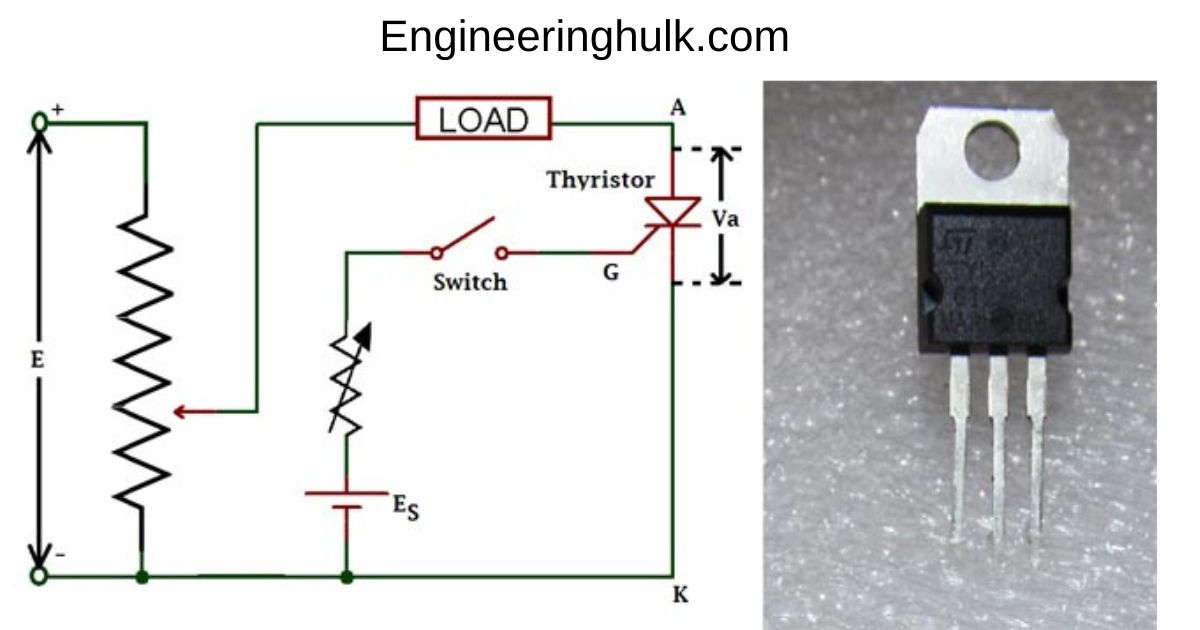
A thyristor is a type of semiconductor device that can act as a switch, controlling the flow of electrical current in a circuit. It is a four-layer semiconductor device with three PN junctions, and it has three terminals: an anode, a cathode, and a gate.
Thyristors are commonly used in power electronics applications where high voltage and/or high current switching is required, such as in electric motors, power supplies, lighting controls, and inverters. They are particularly useful for controlling AC power, as they can be triggered to turn on at a particular point in the AC waveform and then remain on until the waveform crosses zero again.
Some common types of thyristors include silicon-controlled rectifiers (SCRs), gate turn-off thyristors (GTOs), and triacs. SCRs are the most widely used type of thyristor and are typically used for high-power applications. GTOs are similar to SCRs but can be turned off by applying a negative voltage to the gate terminal. Triacs are used for AC power control and are essentially two SCRs connected back-to-back, allowing them to control the flow of current in both directions.
Thyristor symbol
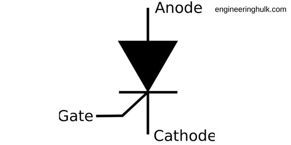
The symbol for a thyristor, also known as a silicon-controlled rectifier (SCR), is typically represented as a four-layer semiconductor device with three terminals: anode (A), cathode (K), and gate (G). The anode and cathode terminals are represented by arrows pointing away from and toward the junction between the P-type and N-type layers, respectively. The gate terminal is represented by a small arrow pointing toward the junction between the P-type and N-type layers, and it is often labeled with the letter “G.” The symbol for a thyristor may also include additional markings to indicate specific characteristics, such as the maximum voltage and current ratings.
Thyristor construction

The construction of a thyristor consists of four layers of alternating P-type and N-type semiconductor material, forming a PNPN structure. There are three junctions in a thyristor: the anode-cathode junction, the cathode-gate junction, and the anode-gate junction.
The thyristor has three terminals: the anode, cathode, and gate. The anode is the positive terminal, the cathode is the negative terminal, and the gate is the control terminal.
The anode and cathode terminals are connected to the PN layers at each end of the device, while the gate terminal is connected to a P-type layer located between the two N-type layers. This P-type layer is called the “gate” layer.
The construction of the thyristor is such that the junction between the anode and the P-type layer of the gate acts as a reverse-biased diode. This means that current cannot flow through this junction unless a voltage is applied that is greater than the breakdown voltage.
When a positive voltage is applied to the anode with respect to the cathode, the anode-cathode junction becomes forward-biased, allowing current to flow through the thyristor. However, the gate terminal remains negative with respect to the anode, which means that the junction between the gate and the P-type layer remains reverse-biased and does not conduct.
If a positive pulse is applied to the gate terminal with respect to the cathode when the anode-cathode junction is forward-biased, it causes a small amount of current to flow through the gate circuit. This current triggers the thyristor, and it switches from a high-resistance state to a low-resistance state, allowing a large current to flow through it.
Once the thyristor is triggered, it remains in the conducting state even if the gate voltage is removed, as long as the anode current is above a certain level called the “holding current.” To turn off the thyristor, the anode current must be reduced to zero, which can be done by reducing the voltage across the anode and cathode or by applying a reverse bias to the anode-cathode junction.
Thyristor working principle
The working principle of a thyristor is based on the concept of p-n-p-n junctions. It has four layers of alternating p-type and n-type semiconductor materials. The three junctions between these layers are the anode junction, cathode junction, and gate junction.
Initially, the thyristor is in a non-conducting state, and no current flows through it. To turn on the thyristor, a positive voltage is applied to its gate terminal with respect to the cathode. This causes a small current to flow into the gate terminal, which triggers a process known as “regeneration.”
During regeneration, a small amount of current flowing into the gate terminal causes a large amount of current to flow from the anode to the cathode through the thyristor. Once the thyristor is turned on, it remains in the conducting state until the current through it falls below a certain threshold level.
To turn off the thyristor, the current flowing through it must be reduced to zero. This can be done by either reducing the voltage applied to the anode or by applying a negative voltage to the gate terminal with respect to the cathode. This negative voltage turns off the thyristor by interrupting the regeneration process.
The thyristor works by using a small current at the gate terminal to trigger a large current flow between the anode and cathode, and it remains in the conducting state until the current through it falls below a certain threshold level or a negative voltage is applied to the gate terminal.
Types of thyristor
There are several different types of thyristors, including:
Silicon-controlled rectifier (SCR):
The SCR is the most commonly used type of thyristor, and it is used for applications such as motor control, lighting, and power supplies.
Gate turn-off thyristor (GTO):
The GTO is a type of thyristor that can be turned off by applying a negative gate current. This allows for greater control over power output and can be used in applications such as inverters, motor control, and high-voltage direct current (HVDC) transmission.
Triac:
The triac is a type of thyristor that can control power flow in both directions. It is commonly used in applications such as dimmer switches and motor control.
Diac:
The diac is a two-terminal device that is often used to trigger other thyristors, such as the triac.
Silicon-controlled switch (SCS):
The SCS is a type of thyristor that is designed for high-frequency switching applications, such as in telecommunications.
Reverse blocking thyristor (RBT):
The RBT is a type of thyristor that is designed to block voltage in the reverse direction. It is often used in applications such as switch-mode power supplies and lighting.
Each type of thyristor has its own unique properties and characteristics, which make them suitable for different applications.
Thyristor uses
Here are some of the most common uses of thyristors:
Power Control:
Thyristors can be used to control high-power AC and DC loads such as motors, heaters, lamps, and power supplies. By controlling the conduction angle of the thyristor, the amount of power delivered to the load can be controlled.
Voltage Regulation:
Thyristors can be used to regulate the output voltage of power supplies and AC voltage controllers. This is achieved by using the thyristor to switch the AC waveform on and off in a controlled manner.
Rectification:
Thyristors can be used as rectifiers to convert AC voltage to DC voltage. In this application, the thyristor acts as a switch that conducts during one half-cycle of the AC waveform and blocks during the other half-cycle, effectively converting the AC voltage to a DC voltage.
Inverter Circuits:
Thyristors can be used in inverter circuits to convert DC voltage to AC voltage. In this application, the thyristors are used to switch the DC voltage on and off in a controlled manner to create an AC waveform.
Lighting Control:
Thyristors are commonly used in lighting control systems to control the brightness of lights. By controlling the conduction angle of the thyristor, the amount of power delivered to the lights can be controlled, thereby controlling their brightness.
Motor Control:
Thyristors can be used to control the speed of AC and DC motors. By controlling the conduction angle of the thyristor, the amount of power delivered to the motor can be controlled, thereby controlling its speed.
Battery Chargers:
Thyristors can be used in battery charger circuits to control the charging current and voltage of batteries.
Overall, thyristors are versatile devices that are widely used in power electronics, motor control, and lighting control applications.
Thyristor applicationss
Here are some common applications of thyristors:
Power control:
Thyristors are widely used in power control circuits such as dimmer switches for lighting, AC motor control, and power supplies for electronic equipment.
Voltage regulation:
Thyristors can be used to regulate the voltage of a circuit by switching on and off at precise times. They are used in voltage regulators for power supplies, battery charging circuits, and voltage stabilizers.
Inverters:
Thyristors are commonly used in inverters, which are circuits that convert DC power to AC power. Inverters are used in many applications, including solar power systems, uninterruptible power supplies, and motor drives.
Welding:
Thyristors are used in welding machines to control the welding current. They provide fast and accurate switching, which is essential for precise welding.
Lighting:
Thyristors are used in lighting circuits to provide dimming control. This allows the brightness of a light to be adjusted to suit different environments and uses less energy than full brightness.
Switched-mode power supplies:
Thyristors are used in switched-mode power supplies to switch the power on and off rapidly. This allows the power supply to be more efficient and produce less heat.
High voltage direct current transmission:
Thyristors are used in high-voltage direct current (HVDC) transmission systems to control the flow of power. HVDC transmission is used to transport electricity over long distances, such as from power plants to cities.
Overall, thyristors have a wide range of applications in various industries such as power electronics, telecommunications, industrial automation, transportation, and many more.
Also, read Type 1 and Type 2 Superconductors



















Comment on “Thyristor in power electronics”
Comments are closed.