 EngineeringHulk
- Home
- Blog
- Automobile Engineering
- Overdrive in Automobile: How an Overdrive Gear Works and When to Use It
Overdrive in Automobile: How an Overdrive Gear Works and When to Use It
On this page
- What is overdrive in an automobile?
- Why cars use overdrive
- How a classic epicyclic overdrive unit works
- Overdrive in modern manual and automatic gearboxes
- Worked example: engine rpm at 100 km/h, direct drive vs overdrive
- When not to use overdrive
- Advantages and disadvantages of overdrive
- References
- FAQs
- Related Topics on EngineeringHulk
Overdrive in an automobile is any gear ratio below 1:1, so the transmission output shaft turns faster than the engine crankshaft. A 0.8:1 overdrive, for example, turns the output shaft 1.25 times for every engine revolution, which lets the car hold a given road speed at about 20 per cent lower engine rpm. It is a cruising gear: it saves fuel, cuts noise and reduces engine wear on long, level runs, at the cost of pulling power.
What is overdrive in an automobile?
A gear ratio is input turns to output turns. First gear might be 3.5:1; top gear in an older four-speed box is usually 1:1, called direct drive, because input and output shafts are locked together. Overdrive goes one step further: at 0.8:1 the output spins faster than the input, and torque falls in the same proportion. The final drive in the axle still provides the big reduction the wheels need, so overall gearing is simply taller than in direct drive.
The term covers two kinds of hardware: a separate overdrive unit, an epicyclic gear set bolted behind the gearbox (the classic arrangement from the late 1940s to the 1980s), and an overdrive gear built into the gearbox itself, which is what “overdrive gearbox” usually means today.
Why cars use overdrive
At a steady 100 km/h on a flat highway a car needs only a small fraction of its engine’s power, so in direct drive the engine spins faster than the job requires. Dropping the rpm with an overdrive ratio gives three benefits:
- Fuel economy. Engine friction and pumping losses rise with rpm. Running slower at a wider throttle opening delivers the same power with less waste.
- Lower noise. Engine noise, intake roar and vibration all fall with rpm, so the cabin is quieter on long drives.
- Less wear. Fewer piston strokes, valve openings and bearing revolutions per kilometre mean slower wear of the engine and its accessories.
How a classic epicyclic overdrive unit works
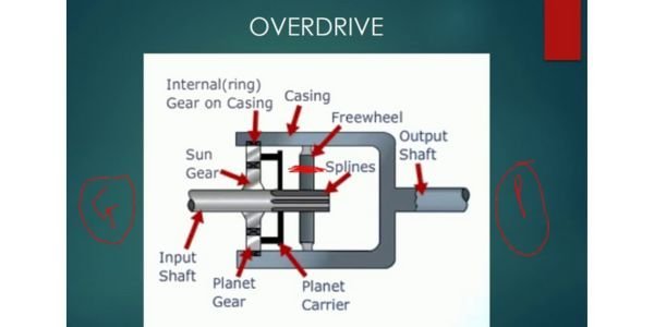
The best-known add-on unit is the Laycock de Normanville overdrive, designed by Edgar de Normanville and built by Laycock Engineering of Sheffield. It first went into production on the 1948 Standard Vanguard and was later fitted to Triumph, MG, Austin-Healey, Jaguar and Volvo cars, among others. It bolts to the back of the gearbox and acts on the gearbox output shaft.
Inside is a single epicyclic (planetary) gear set with three members:
| Member | Connected to | Role in overdrive |
|---|---|---|
| Planet carrier | Splined to the gearbox output shaft, so it is the input | Drives the planet gears around the sun |
| Sun gear | A sliding cone clutch member | Held stationary to give overdrive |
| Annulus (ring gear) | The unit’s output shaft to the propeller shaft | Driven faster than the carrier |
Direct drive (overdrive off). Springs push the cone clutch into the annulus, locking the sun to the annulus. With two members locked together the whole set turns as one solid unit, so output speed equals input speed. A one-way roller clutch between input shaft and annulus also carries drive.
Overdrive (overdrive on). The driver flicks a switch. A solenoid valve lets oil from a small pump driven off the input shaft reach two hydraulic pistons. These overcome the springs and pull the cone clutch away from the annulus and into a brake ring fixed to the casing. The sun gear is now held still. The carrier keeps turning with the input, the planets roll around the stationary sun, and the annulus is forced round faster than the carrier. The one-way clutch simply freewheels, because the annulus is now overrunning the input shaft.
The one-way clutch keeps drive going during the changeover, so the unit shifts without the clutch pedal. An inhibitor switch kept overdrive off in reverse, and on most cars it worked only in the upper gears (typically third and top).
The epicyclic relation behind the ratio
For a simple planetary set, the Willis equation links the speeds (N) and tooth counts (Z) of the sun (s), annulus (a) and carrier (c):
(Ns – Nc) / (Na – Nc) = -Za / Zs
Hold the sun (Ns = 0) and solve for the annulus: Na = Nc x (Za + Zs) / Za. The overdrive ratio, input to output, is therefore:
Overdrive ratio = Za / (Za + Zs)
Take a 20-tooth sun and a 70-tooth annulus (the planets then need (70 – 20) / 2 = 25 teeth). Ratio = 70 / 90 = 0.778:1. That is the familiar Laycock figure: engine speed drops by about 22 per cent. A carrier at 1,000 rpm drives the annulus at 1,000 x 90 / 70 = 1,286 rpm. The sun is always smaller than the annulus, so this ratio is always above 0.5; practical single-stage units sit between roughly 0.7 and 0.85.
Overdrive in modern manual and automatic gearboxes
Separate overdrive units died out once five-speed gearboxes became normal. A modern manual simply makes its top one or two gears overdrive ratios on the layshaft, so no extra hardware is needed. A typical hatchback five-speed has fourth close to 1:1 and fifth near 0.75 to 0.8. Six-speed boxes often have two overdrive gears. You can see a full set of ratios, and why fourth and fifth fall below 1:1, in our guide to the parts of a car transmission. The gear pairs themselves are the ordinary helical pairs described in the constant mesh gear box article.
Automatics already use planetary sets, so overdrive is just another combination of clutches and brakes. Four-speed automatics commonly had a 1:1 third and an overdrive fourth; current six- to ten-speed units have two or more overdrive ratios.
The O/D OFF button on older automatics
Many four-speed automatics had an O/D button on the selector. Pressing it lights “O/D OFF” on the dashboard and stops the gearbox shifting into overdrive fourth. It is not a fault light: it holds the car in third for towing, hills or engine braking without the box hunting between gears. Newer automatics use a manual or tow mode instead.
Worked example: engine rpm at 100 km/h, direct drive vs overdrive
Car: 185/65 R15 tyres, final drive 3.9:1. Compare 4th gear at 1:1 with 5th gear at 0.8:1, both at 100 km/h.
Step 1: tyre size to circumference. The 185 is the section width in mm and 65 is the aspect ratio in per cent, so the sidewall height is 185 x 0.65 = 120.25 mm. The rim is 15 inches, or 15 x 25.4 = 381 mm. Overall diameter = 381 + 2 x 120.25 = 621.5 mm. Free circumference = 3.1416 x 621.5 = 1,952.5 mm. A loaded tyre rolls on a slightly smaller effective radius, so take the rolling circumference as about 97 per cent of that: 1,952.5 x 0.97 = 1,894 mm, or 1.894 m.
Step 2: wheel rpm at 100 km/h. 100 km/h = 100,000 / 60 = 1,666.7 m per minute. Wheel speed = 1,666.7 / 1.894 = 880 rpm.
Step 3: engine rpm in each gear. Engine rpm = wheel rpm x gearbox ratio x final drive.
| Gear | Gearbox ratio | Overall ratio (x 3.9) | Engine rpm at 100 km/h |
|---|---|---|---|
| 4th (direct drive) | 1.00 | 3.90 | 880 x 3.90 = 3,432 |
| 5th (overdrive) | 0.80 | 3.12 | 880 x 3.12 = 2,746 |
| 4th + Laycock unit | 1.00 x 0.778 | 3.03 | 880 x 3.03 = 2,670 |
Fifth saves 686 rpm, exactly 20 per cent, because 1 – 0.8 = 0.2. The price is torque: wheel torque in fifth is also 20 per cent lower than in fourth at the same engine torque, which is why the car feels flat when you ask for acceleration in overdrive. Exam tip: remember the sidewall appears twice in the tyre diameter.
When not to use overdrive
- Towing or carrying a heavy load. The engine labours at low rpm, and in an automatic the box keeps shifting in and out of overdrive, heating the fluid.
- Steep climbs. Drop out of overdrive before the engine starts to lug.
- Long descents. A lower gear gives engine braking and saves the brakes, which is especially relevant on ghat roads.
- Overtaking. Change down, or let the automatic kick down, so the engine is in the rpm range where it makes its torque.
Advantages and disadvantages of overdrive
| Advantages | Disadvantages |
|---|---|
| Lower engine rpm at cruising speed | Less wheel torque, so weak acceleration in overdrive |
| Better highway fuel economy | Poor for towing, climbing and engine braking |
| Quieter cabin and less vibration | A separate unit adds weight, cost, oil and a hydraulic system to maintain |
| Less engine wear per kilometre | Older units could suffer slipping or failure to engage from low oil or a sticking solenoid |
References
FAQs
What is overdrive in an automobile in simple words?
It is a gear ratio lower than 1:1, so the gearbox output shaft spins faster than the engine and the car holds the same road speed at lower rpm, saving fuel and reducing noise and wear.
Is 5th gear an overdrive gear?
In most modern manual cars, yes. Fifth is typically around 0.75 to 0.8:1, below the 1:1 of direct drive. In a six-speed box both fifth and sixth are often overdrive ratios. The exact value is listed in the car’s specification sheet.
How does an epicyclic overdrive unit give a higher output speed?
The input drives the planet carrier and the output is taken from the annulus. When the sun gear is held still by a brake, the planets roll around it and push the annulus round faster than the carrier. The ratio is Za / (Za + Zs), so a 20-tooth sun and 70-tooth annulus give 0.778:1. Locking the sun to the annulus makes the unit turn solid for direct drive.
What does the O/D OFF light mean in an automatic car?
It means the overdrive button has been pressed and the gearbox will not shift into its overdrive gear. It is a driver-selected mode, not a fault. Use it when towing, climbing or descending long hills, and switch it back on for normal cruising.
Related Topics on EngineeringHulk
Keep reading
Alternator in Automobile Engineering: Parts, Working, Voltage Regulation and Testing
How a car alternator works: claw-pole rotor, stator, diode rectifier and regulator, output vs speed, a pulley and belt-load worked example, and testing.

Dynamo in Automobile Engineering: Construction, Working, Control Box and Dynamo vs Alternator
Automobile dynamo meaning, construction for a diagram, working, cut-out and regulator, a worked EMF example, and a clear dynamo vs alternator comparison.

Starting System in Automobile Engineering: Components, Circuit and Working
How the engine starting (cranking) system works: battery, switches, relay, solenoid, series-wound starter motor, drive types, a worked example and faults.
Wheels and Tyres in Automobile Engineering: Difference, Types, Construction and Tyre Size
Difference between wheel and tyre, wheel types, rim terms, tyre construction, radial vs bias ply, and how to read a tyre size like 185/65 R15 88H.
Suspension System in Automobile: Functions, Components and Types
Automobile suspension system explained: functions, springs and shock absorbers, dependent vs independent types, MacPherson strut, ride frequency example.
Steering Geometry in Automobile Engineering: Camber, Caster, KPI, Toe and Ackermann
Steering geometry explained: camber, caster, kingpin inclination, toe-in and Ackermann, with sign conventions, typical angle ranges and alignment faults.