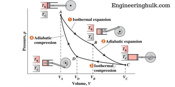
The Carnot cycle is an ideal, fully reversible thermodynamic cycle built from four processes in order: isothermal expansion at the source temperature T_H, reversible adiabatic expansion, isothermal compression at the sink temperature T_C, and reversible adiabatic compression back to the start. Its thermal efficiency depends on nothing but the two reservoir temperatures, η = 1 − T_C/T_H, with both temperatures in kelvin. An engine working between 800 K and 300 K therefore cannot beat 62.5%, whatever fuel, fluid or clever design it uses. Sadi Carnot published the idea in 1824, before the second law of thermodynamics was even written down.
What the Carnot cycle assumes
The Carnot cycle is a thought experiment with a working fluid, usually taken as an ideal gas, sealed in a cylinder with a frictionless piston. Four idealisations hold throughout:
- Two reservoirs of fixed temperature. A hot source at T_H and a cold sink at T_C, both so large that drawing heat from one or dumping it into the other does not change their temperature.
- Every process is reversible. The gas is never more than infinitesimally out of balance with its surroundings, so the cycle can be run backwards and leave no trace.
- No friction anywhere, between the piston and the cylinder or inside the fluid.
- Perfect switching. The cylinder head is a perfect conductor when it sits on a reservoir and a perfect insulator the instant it is moved onto the insulating stand.
Those assumptions are why the cycle sets a ceiling rather than a design. They also tell you what to attack in a real engine: every departure from them costs efficiency.
The four processes of the Carnot cycle
Label the four corner states 1, 2, 3 and 4. The gas starts at state 1, hot and compressed.
1 to 2: reversible isothermal expansion at T_H
The cylinder sits on the hot source. The gas expands and pushes the piston out, so it would cool, but heat flows in from the source at exactly the rate that keeps the temperature pinned at T_H. Pressure falls, volume rises, temperature is constant. Because the internal energy of an ideal gas depends only on temperature, ΔU = 0 and every joule of heat absorbed leaves as work:
Q_H = W_1-2 = m R T_H ln(V2/V1)
2 to 3: reversible adiabatic (isentropic) expansion
The cylinder is moved onto the insulating stand. The gas keeps expanding, but now no heat can enter or leave, so the work comes out of internal energy and the gas cools from T_H to T_C. Q = 0 and entropy is constant:
W_2-3 = m c_v (T_H − T_C), with T_H V2^(γ−1) = T_C V3^(γ−1)
3 to 4: reversible isothermal compression at T_C
The cylinder is placed on the cold sink. The piston pushes in, work is done on the gas, and the heat this would generate is rejected to the sink as fast as it appears, so the temperature stays at T_C. Volume falls, pressure rises, ΔU = 0 again:
Q_C = W_3-4 = m R T_C ln(V3/V4), rejected, not absorbed
4 to 1: reversible adiabatic compression
Back on the insulating stand. Compression continues with no heat transfer, the work done on the gas raises its internal energy, and the temperature climbs from T_C back to T_H, returning the gas to state 1. Q = 0 and T_C V4^(γ−1) = T_H V1^(γ−1).
What happens in each stroke: a summary table
| Process | Type | Pressure | Volume | Temperature | Heat Q | Work W |
|---|---|---|---|---|---|---|
| 1 to 2 | Isothermal expansion at T_H | Falls | Rises | Constant at T_H | +Q_H absorbed from source | +ve, done by gas, equal to Q_H |
| 2 to 3 | Reversible adiabatic expansion | Falls steeply | Rises | Falls T_H to T_C | Zero | +ve, done by gas at the cost of internal energy |
| 3 to 4 | Isothermal compression at T_C | Rises | Falls | Constant at T_C | −Q_C rejected to sink | −ve, done on gas, equal to Q_C |
| 4 to 1 | Reversible adiabatic compression | Rises steeply | Falls | Rises T_C to T_H | Zero | −ve, done on gas, stored as internal energy |
The two adiabatic work terms are numerically equal and opposite, m c_v (T_H − T_C) out and the same in, so they cancel over a complete cycle. What is left as net work is exactly the difference between the two heat quantities: W_net = Q_H − Q_C.
The P-V and T-S diagrams in words
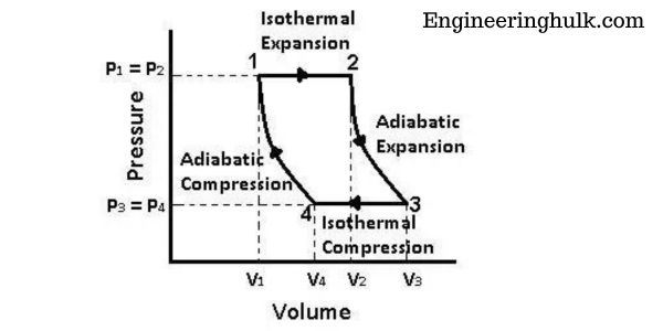
On the P-V diagram the cycle is a closed loop shaped like a tilted, curved wedge, traced clockwise. The two isothermals (1-2 at the top and 3-4 lower down) follow PV = constant, so they are rectangular hyperbolas. The two adiabatics (2-3 and 4-1) follow PV^γ = constant, and since γ is about 1.4 for air, they are steeper than the isothermals wherever the two cross. Four curves, alternating shallow and steep, close the loop. The enclosed area is the net work per cycle. Clockwise means net work out, which is an engine; run the same loop anticlockwise and you have a Carnot refrigerator or heat pump.
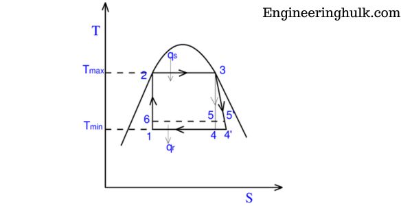
On the T-S diagram the same cycle becomes a plain rectangle, which is why examiners like it. The isothermals are horizontal lines at T_H and T_C. The reversible adiabatics are isentropic, so they are vertical lines at S1 and S2. The area under the top line, T_H × ΔS, is the heat taken in. The area under the bottom line, T_C × ΔS, is the heat rejected. The area inside the rectangle, (T_H − T_C) × ΔS, is the net work. You can read the efficiency straight off the picture as the ratio of the rectangle to the strip beneath it.
Deriving the Carnot efficiency, η = 1 − T_C/T_H
Thermal efficiency is net work out divided by heat in:
η = W_net / Q_H = (Q_H − Q_C) / Q_H = 1 − Q_C/Q_H
Substituting the two isothermal heat quantities:
η = 1 − [T_C ln(V3/V4)] / [T_H ln(V2/V1)]
Now clear the logarithms using the two adiabatic relations. From 2-3, T_H V2^(γ−1) = T_C V3^(γ−1). From 4-1, T_H V1^(γ−1) = T_C V4^(γ−1). Divide the first by the second and the temperatures cancel:
(V2/V1)^(γ−1) = (V3/V4)^(γ−1), and since γ > 1, V2/V1 = V3/V4
The two volume ratios are equal, so the two logarithms are equal and cancel:
η_Carnot = 1 − T_C/T_H
Three things follow immediately. The working fluid has vanished from the result, so it does not matter whether you use air, steam or helium. Efficiency rises if you raise T_H or lower T_C. And η = 1 would need T_C = 0 K or T_H infinite, neither of which is available, so no heat engine can ever convert all its heat into work.
Worked example with real temperatures
A Carnot engine takes heat from a source at 527°C and rejects it to a sink at 27°C. It absorbs 1000 kJ per cycle. Find the efficiency, the work output and the heat rejected.
- Convert to kelvin. T_H = 527 + 273 = 800 K. T_C = 27 + 273 = 300 K. Using celsius here is the single most common mistake in this calculation.
- Efficiency. η = 1 − 300/800 = 1 − 0.375 = 0.625, or 62.5%.
- Work output. W = η × Q_H = 0.625 × 1000 = 625 kJ.
- Heat rejected. Q_C = Q_H − W = 1000 − 625 = 375 kJ. Check it against the ratio: Q_C/Q_H should equal T_C/T_H, and 375/1000 = 0.375 = 300/800. It does.
- Entropy check. Heat absorbed gives ΔS = 1000/800 = 1.25 kJ/K. Heat rejected gives 375/300 = 1.25 kJ/K. They match, so the net entropy change of the universe over one cycle is zero, which is the signature of a reversible cycle.
- Read it off the T-S rectangle. Area = (800 − 300) × 1.25 = 625 kJ, the same work as in step 3.
Now change one temperature at a time, keeping the other fixed, and the practical lesson appears:
- Raise the source by 50 K, to 850 K: η = 1 − 300/850 = 64.7%, a gain of 2.2 percentage points.
- Lower the sink by 50 K, to 250 K: η = 1 − 250/800 = 68.75%, a gain of 6.25 percentage points.
A kelvin off the sink is worth more than a kelvin onto the source, because the sink sits in the numerator of the ratio you are subtracting. That is exactly why power stations fight so hard over condenser vacuum and cooling water temperature, and why the same plant loses output on a hot Indian afternoon in May.
Carnot’s theorem: why nothing can beat it
Carnot’s theorem has two parts, and both are consequences of the second law rather than of any experiment:
- No heat engine operating between two given reservoirs can be more efficient than a reversible engine operating between the same two reservoirs.
- All reversible engines operating between the same two reservoirs have the same efficiency, regardless of working substance or mechanical layout.
The proof is a short argument by contradiction. Suppose some engine X between T_H and T_C were more efficient than a reversible Carnot engine C. Run X forward as an engine, and use part of its work to drive C backwards as a heat pump between the same two reservoirs, sized so that C returns to the hot reservoir exactly the heat that X drew from it. The hot reservoir is now unchanged over the cycle. But X produced more work than C needs, so the combined device delivers net work while exchanging heat with the cold reservoir alone. That is a machine that turns heat from a single reservoir entirely into work, which the Kelvin-Planck statement of the second law forbids. So X cannot exist, and the assumption fails.
The second part follows by swapping the roles of any two reversible engines in the same argument: each would have to be at least as efficient as the other, so they must be equal. This is also what allows the Carnot efficiency to define the thermodynamic (absolute) temperature scale, through Q_H/Q_C = T_H/T_C, independently of any thermometer fluid.
Why the Carnot cycle cannot be built
The cycle is a limit, not a blueprint. Three of its requirements are unachievable in hardware.
- It has to run infinitely slowly. Reversibility demands quasi-static change, with the gas in equilibrium at every instant. A piston that moves at a finite speed sets up pressure and temperature gradients inside the gas, and those gradients generate entropy. An engine that takes infinite time per cycle produces zero power, however efficient it is.
- Isothermal heat transfer needs zero temperature difference. Heat only flows when there is a temperature gap, and any finite gap is irreversible. Transferring a finite quantity of heat across a vanishing difference needs either infinite time or infinite heat exchanger area. Real boilers and condensers work with gaps of tens of kelvin and accept the entropy that creates.
- Friction has to be zero. No piston ring seal is frictionless, no bearing is lossless, and no fluid flows through a valve without pressure drop. Every one of those turns work into heat, which cannot be turned back.
There are practical problems on top of the fundamental ones. Alternately clamping a cylinder to a hot source and a perfect insulator many times a second is not a mechanism anyone has built. The P-V loop is also thin, which means low work per unit of swept volume, so a Carnot engine of useful output would be enormous. And when engineers do try to approach isothermal heat transfer in a cycle, as in the Stirling engine with its regenerator, the mechanical complexity and sealing problems rise quickly.
Link to the second law and entropy
The Carnot cycle is the physical picture behind the entropy definition. For any reversible cycle the Clausius integral of δQ/T around the loop is zero; for the Carnot cycle that is just Q_H/T_H − Q_C/T_C = 0, which the worked example verified as 1.25 = 1.25 kJ/K. For an irreversible cycle the same integral is negative, which is the Clausius inequality, and the shortfall is the entropy generated inside the engine.
That gives a useful way to grade any real machine. Second-law efficiency = actual thermal efficiency ÷ Carnot efficiency between the same two temperatures. A plant running between 800 K and 300 K at an actual 35% has a second-law efficiency of 0.35/0.625 = 56%, and the missing 44% is a direct measure of irreversibility: combustion, finite temperature differences in the heat exchangers, throttling and friction.
Running the cycle in reverse turns it into the ideal refrigerator or heat pump, with the best possible coefficients of performance: COP_ref = T_C/(T_H − T_C) and COP_hp = T_H/(T_H − T_C). For a freezer compartment at 273 K in a kitchen at 303 K, COP_ref = 273/30 = 9.1. A real domestic refrigerator manages roughly 2 to 3, which tells you how much room the ideal leaves.
Carnot compared with the Rankine, Otto and Diesel cycles
Real engines abandon the Carnot shape on purpose, because a buildable cycle with a good power output beats an unbuildable one with a perfect efficiency.
| Cycle | Processes | Where it is used | Ideal efficiency | Typical real efficiency |
|---|---|---|---|---|
| Carnot | 2 isothermal + 2 reversible adiabatic | Nowhere; a reference limit | 1 − T_C/T_H; 62.5% between 800 K and 300 K | Not built |
| Rankine | 2 constant-pressure (boiler, condenser) + 2 isentropic (turbine, pump) | Steam power plants, coal and nuclear | Around 45 to 50% for supercritical steam conditions | About 33 to 38% for subcritical units, up to roughly 45% for ultra-supercritical plants |
| Otto | 2 isentropic + 2 constant-volume | Petrol and CNG spark-ignition engines | 1 − 1/r^(γ−1); 58.5% at r = 9, γ = 1.4 | About 25 to 35% brake thermal; the best modern engines exceed 40% at one favourable operating point |
| Diesel | 2 isentropic + constant-pressure heat addition + constant-volume rejection | Trucks, gensets, locomotives, ships | 63.2% at r = 18 with cut-off ratio 2 and γ = 1.4 | About 35 to 42% in road engines, around 50% for large low-speed marine two-strokes |
Two honest points about that table. First, the ideal figures for Otto and Diesel are air-standard numbers, computed for a cold air cycle with constant specific heats, so they sit well above what the same engine achieves on a dynamometer. Second, the Carnot number is not a fair target for any of them, because Otto and Diesel add heat over a sliding temperature range rather than at a single T_H. The Rankine cycle is the closest relative, since boiling and condensing really do happen at constant temperature, and a Rankine cycle without superheat is essentially a Carnot cycle squeezed under the saturation dome. It is abandoned there for a mechanical reason: compressing a wet vapour mixture wrecks the pump, so the working fluid is condensed fully to liquid first.
References
- NCERT Physics, Class 11, Chapter on Thermodynamics – Carnot engine and Carnot’s theorem.
- NPTEL – Engineering Thermodynamics lecture series, IIT.
FAQs
What are the four processes of the Carnot cycle in order?
Reversible isothermal expansion at the source temperature T_H, in which heat Q_H is absorbed; reversible adiabatic expansion, in which the gas cools from T_H to T_C with no heat transfer; reversible isothermal compression at the sink temperature T_C, in which heat Q_C is rejected; and reversible adiabatic compression, which returns the gas to T_H and to its starting state.
What is the efficiency formula for a Carnot cycle?
η = 1 − T_C/T_H, where T_C is the sink temperature and T_H the source temperature, both in kelvin. It comes from η = 1 − Q_C/Q_H once the adiabatic relations show that V2/V1 = V3/V4, which makes the two logarithmic terms cancel. Between 800 K and 300 K the efficiency is 62.5%.
Why is the Carnot cycle impossible in practice?
Because every step must be reversible. That needs the engine to run infinitely slowly, heat to cross a zero temperature difference during the isothermal strokes, and friction to be completely absent. An infinitely slow engine delivers zero power, zero temperature difference needs infinite heat exchanger area, and no real piston or bearing is frictionless.
Why is the Carnot cycle a rectangle on a T-S diagram?
The two isothermal processes happen at fixed temperature, giving horizontal lines at T_H and T_C. The two reversible adiabatic processes are isentropic, so entropy is fixed and they give vertical lines. The enclosed rectangle has area (T_H − T_C) × ΔS, which is the net work of the cycle.
Does the working fluid change the Carnot efficiency?
No. The fluid cancels out of the derivation, and Carnot’s theorem states that all reversible engines between the same two reservoirs have the same efficiency. Air, steam, helium or any other substance gives 1 − T_C/T_H. The fluid affects the size of the machine and the work per cycle, not the efficiency ceiling.
Related Topics on EngineeringHulk
- 👉 Carnot Cycle – Thermodynamics Study Guide
- 👉 Rankine Cycle – Study Guide
- 👉 Thermodynamics – Study Guide
- 👉 Heat Transfer
- 👉 Carnot Cycle MCQ – Objective Questions with Answers
- 👉 Otto Cycle
- 👉 Second Law of Thermodynamics MCQ – Objective Questions with Answers
- 👉 Diesel Cycle MCQ – Objective Questions with Answers
- 👉 First Law of Thermodynamics