 EngineeringHulk
- Home
- Blog
- Automobile Engineering
- Types of Final Drive in Automobiles: Bevel, Hypoid, Worm, Double-Reduction and Chain
Types of Final Drive in Automobiles: Bevel, Hypoid, Worm, Double-Reduction and Chain
On this page
- What does the final drive do?
- Types of final drive at a glance
- How the final drive gear ratio is found
- Final drive ratio: acceleration, top speed and fuel use
- Worked example: 3.9 versus 4.3 final drive in top gear
- The differential, in one paragraph
- Common final drive faults
- FAQs
- Related Topics on EngineeringHulk
The final drive is the last speed-reduction stage between the gearbox and the driven wheels. In a rear-wheel-drive car it is the crown wheel and pinion in the rear axle, which reduces speed by about 3:1 to 4.5:1, multiplies torque by the same factor and turns the drive through 90 degrees. The main types of final drive are straight bevel, spiral bevel, hypoid, worm and worm wheel, double-reduction, helical (in front-wheel-drive transaxles) and chain or belt drive (on motorcycles). This page explains each type, how the final drive ratio changes acceleration, top speed and fuel use, and works through a 3.9 versus 4.3 ratio example.
What does the final drive do?
The engine and gearbox turn far too fast for the wheels. Even in top gear, the propeller shaft of a car at highway speed spins at around 2,500 to 3,500 rpm, while the wheels turn at under 1,000 rpm. The final drive supplies that last fixed reduction. It has three jobs:
- Permanent speed reduction and torque increase. A 4:1 final drive turns the wheels once for every four turns of the propeller shaft and multiplies the torque about four times, less a few percent lost to friction.
- A 90 degree turn in the drive. In a front-engine, rear-wheel-drive layout the propeller shaft runs along the car, but the axle shafts run across it. Bevel-type gears make that turn.
- Carrying the differential. The crown wheel is bolted to the differential cage, so the final drive and the differential sit together in one housing and are often sold as one unit.
The power path runs: engine, clutch, gearbox, propeller shaft and universal joints, final drive, differential, axle shafts, wheels. The parts of a car transmission page follows that whole chain.
Types of final drive at a glance
| Type | Gear arrangement | Main strength | Main drawback | Typical use |
|---|---|---|---|---|
| Straight bevel | Straight teeth on cone-shaped gears, axes intersect | Simple and cheap to make | Noisy, one tooth pair carries the load at a time | Early cars, slow machinery, differential side gears |
| Spiral bevel | Curved, angled teeth, axes intersect | Quieter and stronger than straight bevel | Produces axial thrust, needs taper roller bearings | Some cars, motorcycles with shaft drive, gear heads |
| Hypoid | Spiral-type teeth, pinion axis offset below the crown wheel centre | Quiet, strong, lets the floor sit lower | High tooth sliding, needs hypoid (EP) gear oil | Most rear-wheel-drive cars, pickups and trucks |
| Worm and worm wheel | Screw-like worm driving a toothed wheel, axes at 90 degrees but not intersecting | Very large reduction in one stage, silent | Lower efficiency, heat, bronze wheel wears | Older cars and buses, some heavy trucks |
| Double-reduction | Bevel or hypoid stage plus a second spur, helical or planetary stage | High total ratio with a smaller crown wheel and more ground clearance | More parts, cost and weight | Heavy trucks, buses, tractors, off-road vehicles |
| Helical (transaxle) | Helical gears on parallel shafts, no 90 degree turn | Compact, quiet, efficient | Only suits transverse engines | Front-wheel-drive cars |
| Chain or belt | Sprockets or pulleys on parallel shafts | Light, cheap, easy to change the ratio | Needs cleaning, lubrication and adjustment | Motorcycles, scooters, bicycles |
Straight bevel gear final drive
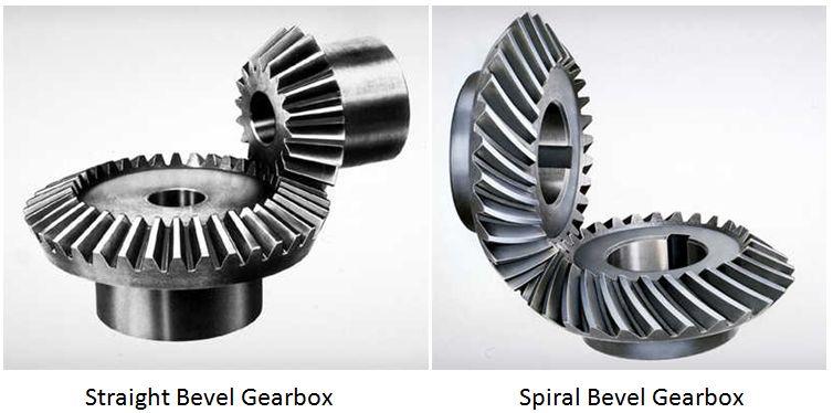
Both gears are cones with straight teeth that point towards the meeting point of the two shafts. The teeth engage all at once along their length, so each tooth takes the load with a small impact. That makes them noisy at speed and limits the load they carry. They are rarely used as the main final drive in modern vehicles, though the small planet and side gears inside a typical open differential are still straight bevel gears. For the geometry of bevel teeth, see the types of gears page.
Spiral bevel gear final drive
The teeth are curved and set at an angle, so contact starts at one end of a tooth and rolls across it. More than one tooth pair is in contact at a time, which spreads the load and cuts noise. The pinion axis still passes through the crown wheel axis. The curved teeth push the gears apart along their axes, so the pinion runs in preloaded taper roller bearings.
Hypoid gear final drive
A hypoid set looks like a spiral bevel set, but the pinion axis is offset from the crown wheel axis, usually below it in a car. That offset has three effects:
- The propeller shaft can sit lower, so the body floor and its central tunnel can be lower.
- The pinion can be larger and stronger for the same ratio, and more teeth are in contact, so it runs quietly.
- The teeth slide across each other as well as rolling. That sliding creates heat and very high contact pressure.
Because of the sliding, hypoid axles need hypoid gear oil with extreme-pressure (EP) additives, normally an API GL-5 grade such as 80W-90. Ordinary engine oil or a light gearbox oil will let the teeth score. Hypoid is the standard final drive in rear-wheel-drive cars and commercial vehicles today.
Worm and worm wheel final drive
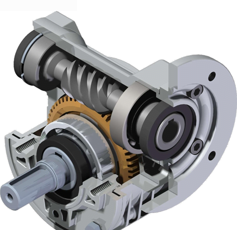
A steel worm, like a coarse screw, meshes with a worm wheel, usually bronze. The ratio equals the worm wheel teeth divided by the number of starts on the worm, so a large reduction fits in one compact stage. The drive is very quiet and can be placed above or below the wheel, which suited buses and trucks that needed a low floor or high ground clearance. The price is friction: worm teeth slide almost all the time, so efficiency is lower than bevel or hypoid gears and the unit runs hot. Peugeot used worm-drive rear axles on cars up to the 404 in the 1960s, but hypoid gears have replaced the worm in almost all road vehicles.
Double-reduction final drive
A heavy truck needs an overall axle ratio of 5:1 to 7:1 or more. Getting that from one bevel stage would need a huge crown wheel, which eats ground clearance. A double-reduction axle splits the job: a bevel or hypoid pair gives the first reduction and turns the drive through 90 degrees, then a spur, helical or planetary set gives the second. In hub-reduction axles the second stage is a small planetary set inside each wheel hub, so the axle shafts and differential carry less torque. Some trucks have a two-speed axle that lets the driver switch between a high and a low final drive ratio.
Helical final drive in front-wheel-drive transaxles
In a front-wheel-drive car with a transverse engine, the crankshaft, gearbox shafts and axle shafts all lie across the car. No 90 degree turn is needed, so the final drive is a small helical pinion on the gearbox output shaft meshing with a large helical gear bolted to the differential. The gearbox and final drive share one casing, called a transaxle. Most Indian hatchbacks and compact sedans use this layout. Cars that combine a lengthwise-mounted engine with a transaxle, such as rear-engined cars and some front-wheel-drive Audis, still need a bevel or hypoid pair inside it.
Chain and belt final drive
Most motorcycles use a roller chain from a small gearbox sprocket to a large rear-wheel sprocket. The ratio is the rear sprocket teeth divided by the front sprocket teeth, for example 42/14 = 3.0. Some motorcycles use a toothed belt, and larger touring bikes use a shaft with a bevel final drive at the rear wheel. Scooters with a CVT use a belt and a small gear reduction at the rear wheel.
How the final drive gear ratio is found
The final drive ratio is the number of crown wheel teeth divided by the number of pinion teeth. A crown wheel with 41 teeth driven by an 11-tooth pinion gives:
Final drive ratio = 41 ÷ 11 = 3.727, written 3.73:1
The propeller shaft turns 3.73 times for each turn of the crown wheel. Tooth counts are often stamped on the crown wheel face, which is how a mechanic identifies the ratio. Designers pick tooth counts with no common factor (41 and 11 share none) so that each pinion tooth meets every crown wheel tooth in turn, which spreads wear evenly.
Final drive ratio: acceleration, top speed and fuel use
Final drive transmission ratio works together with the gearbox. The overall ratio in any gear is:
Overall ratio = gearbox ratio × final drive ratio
- A numerically higher final drive (for example 4.3) gives more wheel torque in every gear, so the car accelerates and climbs better and pulls a load more easily. The engine turns faster at a given road speed, so cruising fuel use and noise rise.
- A numerically lower final drive (for example 3.9) lets the engine turn slower at cruise, which helps fuel economy, but the car feels less eager and may not reach the engine’s peak power in top gear.
Goods vehicles and off-road vehicles therefore use higher ratios than highway cars. An overdrive top gear, below 1:1, lets a car keep a higher final drive for acceleration while still cruising at low rpm.
Worked example: 3.9 versus 4.3 final drive in top gear
Take a car with these figures:
- Engine speed 3,000 rpm, engine torque 140 N·m at that speed
- Top (5th) gear ratio 0.80
- Tyre rolling radius 0.30 m, so the wheel travels 2π × 0.30 = 1.885 m per turn
- Driveline losses ignored, to keep the arithmetic clear
Step 1: overall ratio.
- With 3.9: 0.80 × 3.9 = 3.12
- With 4.3: 0.80 × 4.3 = 3.44
Step 2: wheel speed.
- With 3.9: 3,000 ÷ 3.12 = 961.5 rpm
- With 4.3: 3,000 ÷ 3.44 = 872.1 rpm
Step 3: road speed = wheel rpm × 1.885 m × 60 ÷ 1,000
- With 3.9: 961.5 × 1.885 × 0.06 = 108.7 km/h
- With 4.3: 872.1 × 1.885 × 0.06 = 98.6 km/h
Step 4: torque at the driving wheels = engine torque × overall ratio (shared between the two wheels by the differential)
- With 3.9: 140 × 3.12 = 436.8 N·m, a tractive force of 436.8 ÷ 0.30 = 1,456 N
- With 4.3: 140 × 3.44 = 481.6 N·m, a tractive force of 481.6 ÷ 0.30 = 1,605 N
Result. The 4.3 final drive gives about 10 percent more wheel torque (4.3 ÷ 3.9 = 1.103) but about 10 percent less road speed at the same engine rpm. Put the other way, at a steady 100 km/h in top gear the engine turns at about 2,760 rpm with the 3.9 ratio and about 3,040 rpm with the 4.3 ratio. A real driveline loses a few percent more at the hypoid gears, bearings and joints, so real wheel torque is slightly lower than these figures.
The differential, in one paragraph
When a car turns, the outer driven wheel travels further than the inner one. If both were fixed to the crown wheel, one tyre would have to scrub. The differential is a small set of bevel gears inside a cage bolted to the crown wheel: two or four planet (pinion) gears on a cross-pin mesh with two side gears splined to the axle shafts. Driving straight, the whole cage turns as one block. In a turn, the planet gears rotate on their pin and let one side gear run faster than the other, while the torque stays split equally. The differential page covers limited-slip and locking types, and the types of axles page covers the housings that carry the final drive.
Common final drive faults
- Whine that changes with road speed: worn or poorly set crown wheel and pinion mesh, or worn pinion bearings. A whine on acceleration but not on overrun (or the reverse) points to the tooth contact pattern.
- Clunk when taking up drive: excess backlash between crown wheel and pinion, worn differential pins or worn splines.
- Rumble or growl: worn pinion or carrier bearings.
- Oil leaks: a failed pinion oil seal at the front of the axle, or axle shaft seals. Low oil soon destroys hypoid gears.
- Scored or pitted teeth: the wrong oil (no EP additive in a hypoid axle), overloading or overheating.
Setting up a new crown wheel and pinion means adjusting pinion depth with shims, bearing preload and backlash (often around 0.1 to 0.2 mm on a car axle, but always use the maker’s figure), then checking the tooth contact pattern with marking compound.
FAQs
What are the types of final drive?
The main types are straight bevel, spiral bevel, hypoid, worm and worm wheel, double-reduction, helical final drive in front-wheel-drive transaxles, and chain or belt final drive on motorcycles. Hypoid is the most common in rear-wheel-drive cars and trucks.
What is a final drive gear?
It is the gear pair that makes the last fixed speed reduction before the wheels. In a rear-wheel-drive car it is the crown wheel and pinion in the rear axle; in a front-wheel-drive car it is a helical gear pair on the differential inside the transaxle.
How is the final drive ratio calculated?
Divide the crown wheel teeth by the pinion teeth. A 41-tooth crown wheel and an 11-tooth pinion give 41 ÷ 11 = 3.73:1. The overall ratio in any gear is the gearbox ratio multiplied by the final drive ratio.
Why do hypoid final drives need special oil?
The offset pinion makes the teeth slide across each other under high load. Hypoid gear oil, usually API GL-5, carries extreme-pressure additives that stop the tooth surfaces welding and scoring.
Is a higher final drive ratio better?
It depends on the use. A numerically higher ratio gives more wheel torque and quicker acceleration but higher engine rpm and fuel use at cruise. A lower ratio does the reverse, which suits highway driving.
Related Topics on EngineeringHulk
Keep reading
Lead Acid Battery in Automobiles: Construction, Working and Types
Lead acid battery construction explained part by part: plates, grids, separators, electrolyte, cell chemistry, SMF/AGM/EFB types, ratings and a worked example.

Chassis Frame: Definition, Types of Chassis and Materials
Types of chassis explained: ladder, monocoque, backbone, tubular, perimeter, X-frame, platform and EV skateboard, with materials and a rigidity table.

What Is a Clutch? Parts, Working and Types of Clutches
A clutch connects and disconnects the engine from the gearbox. Clutch parts, how it works, 8 types (single-plate, multi-plate, cone, centrifugal) and faults.
Types of Gears: Classification, Comparison and Applications
Types of gears by shaft layout: spur, helical, herringbone, rack, bevel, worm, hypoid and crossed helical, with efficiency table, uses and worked examples.
Battery Charging Methods in Automobiles: How a Car Battery Is Charged
What charges a car battery, and how workshops charge one: constant current, constant voltage, 3-stage smart, trickle, boost and equalising, worked example.

Bendix Drive in a Starter Motor: Working, Construction and Modern Alternatives
How a Bendix drive engages and throws out the starter pinion, its parts and failure modes, plus inertia vs pre-engaged starter drives compared.