
A CNC mill (CNC milling machine) is a milling machine whose table and spindle movements are driven by servo motors under a computer program, so a rotating multi-point cutter removes metal along exact X, Y and Z paths without a hand on the wheels. Most shop-floor CNC mills are 3-axis vertical machining centres (VMCs); horizontal machining centres (HMCs) and 4- and 5-axis machines handle larger batches and more complex shapes. The program is written in G-code and M-code, usually generated by CAM software.
This page is about the milling machine itself: its types, parts, how a program runs on it and where it is used. For the general idea of numerical control and how it differs from conventional machines, read what is computer numerical control (CNC).
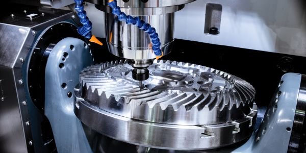
How does a CNC mill work?
The cutter rotates in the spindle while the machine moves the cutter and the workpiece relative to each other along the programmed path. On a typical VMC the table carries the part in X (left-right) and Y (front-back), and the spindle head moves in Z (up-down). Each axis has a servo motor turning a ball screw, and a rotary encoder or linear scale reports the real position back to the controller. The controller compares the commanded and actual positions thousands of times a second and corrects the error, which is what makes the motion accurate and repeatable. This feedback arrangement is called a closed-loop system.
The workflow in a shop runs like this:
- The part is modelled in CAD.
- CAM software turns the model into toolpaths, picking the cutters, speeds and feeds.
- A post-processor converts the toolpaths into G-code for that particular controller (Fanuc, Siemens, Heidenhain and so on).
- The program is loaded into the machine by USB, network or, on older machines, a DNC link.
- The operator clamps the part, sets the tool lengths and the work offset, proves out the program, then runs production.
Main parts of a CNC milling machine
| Part | What it does |
|---|---|
| Bed and column | Heavy cast-iron or polymer-concrete structure that carries everything and damps vibration |
| Spindle | Holds the tool (BT, CAT or HSK taper) and rotates it; power and speed decide what materials and cutters the machine can use |
| Table / saddle | Carries the vice, fixture or part and moves it in X and Y (T-slots for clamping) |
| Axis drives | Servo motors, ball screws and linear guideways that move each axis |
| Automatic tool changer (ATC) | Carousel or chain magazine plus a changer arm that swaps tools on an M06 command, commonly in a few seconds |
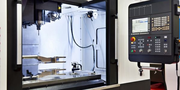
| Controller (CNC unit) | Reads the program, calculates the interpolated path and commands the drives; also stores tool and work offsets |
| Feedback devices | Encoders or linear scales that report actual axis position |
| Coolant and chip system | Pumps coolant to the cut (M08/M09) and carries chips out with a conveyor |
| Enclosure | Guards the operator from chips and coolant; door interlocks stop the spindle when opened |
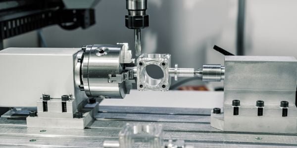
Types of CNC mills
Vertical machining centre (VMC)
The spindle axis is vertical and the cutter comes down onto the part. VMCs are cheaper, easy to set up and easy to watch, so they are the standard machine in job shops, toolrooms and B.Tech workshops. Their weakness is chip evacuation in deep pockets, because chips fall back into the cut.
Horizontal machining centre (HMC)
The spindle is horizontal and the part usually sits on a rotary indexing table. Chips fall away by gravity, and the rotary table lets the machine reach four sides of a part in one clamping. Many HMCs have twin pallets: the operator loads the next part on one pallet while the other is inside being machined. That is why HMCs dominate high-volume work such as engine blocks, gearbox housings and valve bodies, at a much higher purchase price.
3-axis, 4-axis and 5-axis mills
- 3-axis: linear X, Y and Z only. Good for plates, pockets, slots, holes and most prismatic parts. Features on other faces need the part to be re-clamped.
- 4-axis: adds one rotary axis, usually an A axis turning about X (a rotary table or trunnion on a VMC, or the B-axis index table on an HMC). Used for cams, holes around a shaft, and machining several faces in one setup.
- 5-axis: two rotary axes, either tilting the table (trunnion) or tilting the head. In 3+2 machining the rotary axes lock at an angle and the cut is done in 3 axes; in simultaneous 5-axis all five move together, which is needed for turbine blades, impellers, orthopaedic implants and mould cores with deep, steep walls.
How a CNC mill program runs: G-code and M-code basics
A program is a list of blocks, one instruction line each. G-codes set the type of motion and the modes; M-codes switch machine functions on and off. The most used codes on a Fanuc-style control are:
| Code | Meaning |
|---|---|
| G00 | Rapid move (positioning, not cutting) |
| G01 | Straight-line cutting move at feed F |
| G02 / G03 | Circular arc, clockwise / counter-clockwise |
| G17 | XY plane selected for arcs |
| G21 / G20 | Millimetre / inch units |
| G90 / G91 | Absolute / incremental coordinates |
| G43 H__ | Apply tool length offset |
| G54 to G59 | Select a work offset (part zero) |
| M03 / M04 / M05 | Spindle clockwise / counter-clockwise / stop |
| M06 | Tool change |
| M08 / M09 | Coolant on / off |
| M30 | End of program and rewind |
A short real example
The program below uses a 10 mm end mill to cut a 3 mm deep path: a straight line along X, a 20 mm radius corner turning left, then a straight line along Y.
O1001 (SLOT WITH R20 CORNER)
G21 G17 G90 G40 G80
T02 M06            (10 mm end mill)
G54                (part zero)
S2400 M03          (spindle 2400 rpm clockwise)
G00 X0 Y0
G43 Z25.0 H02 M08  (tool length offset, coolant on)
G00 Z2.0
G01 Z-3.0 F100     (plunge 3 mm deep)
G01 X40.0 F400     (cut along X)
G03 X60.0 Y20.0 R20.0  (R20 arc, counter-clockwise)
G01 Y50.0          (cut along Y)
G00 Z25.0 M09
M05
G91 G28 Z0         (Z to home)
M30
Line by line: the first block sets millimetres, the XY plane, absolute mode and cancels old compensation and cycles. M06 loads tool 2. G54 tells the machine where the part zero is. The arc runs from (40, 0) to (60, 20) about a centre at (40, 20), so it is counter-clockwise and the path turns smoothly from the X direction into the Y direction. Using G02 with the same end point would curve the wrong way and leave a sharp corner.
The spindle speed follows from N = 1000V / (πD). At 2400 rpm on a 10 mm cutter, V = π × 10 × 2400 / 1000 = 75.4 m/min, a reasonable figure for an HSS or light carbide cut in aluminium. You can check other combinations with the cutting speed and RPM calculator. The feed of 400 mm/min on a 2-flute cutter gives 400 / (2400 × 2) = 0.083 mm per tooth.
Work offsets and tool offsets
The machine has its own fixed zero, the machine home. The drawing is dimensioned from a point on the part. A work offset (G54 to G59) stores the distance from machine home to that part zero, measured by the operator with an edge finder or probe. If the same program is run on a second vice, only a different offset (say G55) is needed, not a new program.
A tool length offset (G43 with an H number) stores how far each tool sticks out of the spindle, so every tool reaches the same Z zero. Cutter radius compensation (G41 left, G42 right, G40 cancel) shifts the path by the cutter radius so the program can follow the drawing contour directly, and a worn or reground tool is handled by editing one number.
Operations done on a CNC mill
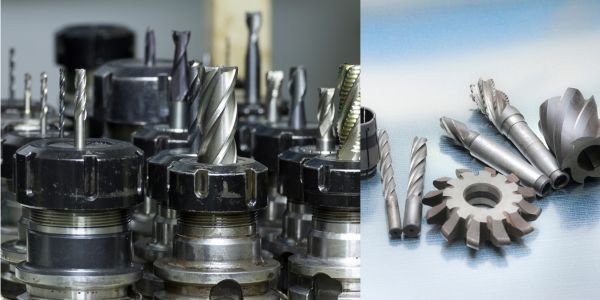
Face milling, side and slot milling, pocketing, contouring and 3D surfacing, drilling, reaming, tapping and boring (using canned cycles such as G81 drilling, G83 peck drilling and G84 tapping), thread milling and engraving. The choice of cutter for each operation is covered in milling cutter types and applications.
Advantages and limitations of CNC mills
| Advantages | Limitations |
|---|---|
| Repeatable accuracy from part to part; hundredths of a millimetre are routine | High capital cost, plus tooling, fixtures and CAM software |
| Complex contours and 3D surfaces that are impractical by hand | Needs trained programmers and setters |
| One operator can run more than one machine; lights-out running with pallets | Setup and prove-out time makes one-off simple parts slow compared with a manual mill |
| Program stored, so repeat orders need no re-learning | A programming error can crash the spindle into the part or fixture |
| Fewer setups on 4/5-axis machines, so fewer errors | Poor finish or tolerance on hardened parts may still need grinding |
Applications of CNC milling machines
- Automotive: cylinder heads, engine blocks, gearbox housings, brackets.
- Aerospace: structural aluminium frames, titanium brackets, blisks and turbine blades on 5-axis machines.
- Tool and die: injection mould cores and cavities, press tool parts, electrodes for EDM.
- Medical: hip and knee implants, surgical instruments.
- General engineering: fixtures, valve bodies, pump parts and prototypes.
A little history: the first numerically controlled milling machine was built at MIT’s Servomechanisms Laboratory and demonstrated in 1952, following the work of John T. Parsons on machining helicopter rotor blade templates. It was a modified Cincinnati Hydro-Tel mill. Student tip: for B.Tech exams on part programming, practise writing G01/G02/G03 blocks by hand and checking arc direction. NPTEL’s manufacturing process courses cover the same material.
FAQs
What is the difference between a CNC mill and a CNC lathe?
In a CNC mill the cutter rotates and the workpiece is held still on a moving table, so it makes flat faces, pockets and 3D shapes. In a CNC lathe the workpiece rotates and a single-point tool cuts it, so it makes round parts such as shafts and bushes.
What is the difference between a VMC and an HMC?
A VMC has a vertical spindle and is cheaper and simpler. An HMC has a horizontal spindle, usually with a rotary table and pallet changer, so it clears chips better, reaches four sides in one clamping and suits high-volume production.
What do G00 and G01 mean in CNC milling?
G00 is a rapid positioning move at the machine’s maximum traverse speed, used only in clear air. G01 is a straight-line cutting move at the programmed feed rate F.
What is G54 in a CNC mill program?
G54 selects the first work offset, the stored distance from machine home to the part zero. G55 to G59 are further offsets for extra fixtures or parts.
When is a 5-axis CNC mill needed?
When the part has undercuts or surfaces that a 3-axis cutter cannot reach, such as turbine blades, impellers or deep mould cavities, or when you want to machine five faces in one setup to avoid re-clamping errors.