Curves in Surveying
Simple Circular Curves, Transition Curves, Compound Curves & Vertical Curves
Last Updated: April 2026 | GATE CE 2025–2027
📌 Key Takeaways
- Curves connect two straights where the direction changes — classified as horizontal (circular/spiral) and vertical (parabolic).
- Tangent length: T = R·tan(Δ/2); arc length: L = πRΔ/180; long chord: LC = 2R·sin(Δ/2).
- Setting out by linear methods (offsets from long chord, bisection) or angular method (Rankine’s deflection angles).
- Transition curve: provides gradual change from infinite radius (straight) to R (circular); length determined from superelevation runoff or comfort criterion.
- Compound curve: two circular arcs of different radii with a common tangent; solved using the common tangent line.
- Vertical curves are parabolic (not circular) — easier to design and set out, and give constant rate of change of gradient.
- Summit curve design: based on SSD/OSD; Sag curve: based on headlight distance or comfort.
1. Classification of Curves
| Type | Sub-type | Description |
|---|---|---|
| Horizontal | Simple circular | Single arc of constant radius connecting two tangents |
| Compound | Two or more circular arcs of different radii on the same side | |
| Reverse | Two circular arcs of opposite curvature (S-shaped) — avoided in highways due to sudden change | |
| Transition (Spiral) | Euler spiral/Clothoid | Radius gradually changes from ∞ to R; placed between straight and circular curve |
| Vertical | Summit (crest) | Rising then falling grade; design based on SSD/OSD |
| Sag (valley) | Falling then rising grade; design based on headlight distance |
In Indian highway design (IRC standards), composite curves (transition + circular + transition) are preferred over simple circular curves on high-speed roads to ensure smooth change in centrifugal force and superelevation.
2. Elements of a Simple Circular Curve
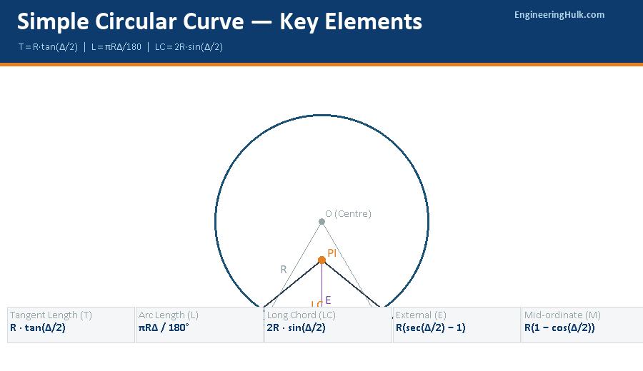
Curve Geometry & Elements
Δ = Deflection angle (angle of deviation of the two tangents) = I (intersection angle at PI)
Tangent length: T = R · tan(Δ/2)
Arc length: L = πRΔ/180 (Δ in degrees)
Long chord: LC = 2R · sin(Δ/2)
External distance: E = R(sec(Δ/2) − 1) = R(1/cos(Δ/2) − 1)
Mid-ordinate: M = R(1 − cos(Δ/2))
Versed sine: V = R(1 − cos(Δ/2)) = M
Chainage of T₁ = Chainage of PI − T
Chainage of T₂ = Chainage of T₁ + L
The Point of Intersection (PI) or Vertex (V) is where the two tangents meet. T₁ (or PC — Point of Curvature) is where the curve begins; T₂ (or PT — Point of Tangency) is where it ends. The apex (or crown) is the midpoint of the arc, located at distance E from the PI along the bisector of the deflection angle.
Degree of curve (D): In chord definition (India), D = 1718.87/R minutes, where R is in metres. In arc definition (USA), D = 5729.58/R.
3. Setting Out Methods
Linear Methods
- Offsets from long chord: Ox = √(R² − x²) − √(R² − (LC/2)²), where x is measured from the midpoint of the long chord. O₀ (at midpoint) = M (mid-ordinate).
- Offsets from tangents (perpendicular): Ox = R − √(R² − x²) ≈ x²/2R for small curves. x measured along the tangent from T₁.
- Successive bisection of arcs: Bisect the long chord to get the crown, then bisect each half-chord — quick but tedious for many pegs.
Angular Method — Rankine’s Deflection Angle
Deflection angle for chord Cn: δn = (Cn × 1719) / R (minutes)
Or: δn = (Cn × 90) / (πR) degrees = Cn / (2R) radians
Total deflection angle to peg n = Σδ₁ + δ₂ + … + δn
Check: Total deflection angle from T₁ to T₂ = Δ/2
Rankine’s method is the most accurate angular method. Theodolite set at T₁, telescope oriented along T₁–PI direction (0° reading). Each peg is located by turning the cumulative deflection angle from the initial direction and measuring the chord length from the previous peg with a tape.
4. Compound & Reverse Curves
A compound curve consists of two or more simple circular arcs of different radii curving in the same direction, with a common tangent at the point of compound curvature (PCC). The key parameters: R₁, R₂, Δ₁ (deflection of first arc), Δ₂ (deflection of second arc), with Δ = Δ₁ + Δ₂ as the total deflection angle.
Compound Curve — Common Tangent Length
T₁ = R₁·tan(Δ₁/2), T₂ = R₂·tan(Δ₂/2)
Length of common tangent: t = T₁ + T₂
From PI, the common tangent point divides the common tangent in ratio T₁ : T₂
A reverse curve consists of two arcs curving in opposite directions with a common tangent at the point of reverse curvature (PRC). Reverse curves are avoided on highways because drivers must suddenly steer from left to right (or vice versa) without a straight transition, causing accidents at high speeds. They are permissible on railways only at very low speeds.
5. Transition (Spiral) Curves
A transition curve provides a gradual change of radius from ∞ (straight) to R (circular curve). This allows superelevation and widening to be introduced progressively. Without a transition curve, drivers experience a sudden jerk as the centrifugal force jumps from 0 to mv²/R at the tangent point.
Length of Transition Curve
By rate of change of centrifugal acceleration: L = v³ / (C · R)
C = 0.3 m/s³ (IRC recommendation for highways), v in m/s, R in m
By superelevation runoff: L = e · N · v / (2 × lateral gradient)
Empirical (IRC): L = 2.7v² / R (v in km/h, R in m)
Design length = Maximum of the above three values.
Shift (s) of circular curve: s = L² / (24R) (curve shifts inward to accommodate the transition)
Total tangent length with transition: T = (R + s)·tan(Δ/2) + L/2
The Euler spiral (clothoid) is the most common transition curve where the radius is inversely proportional to the distance along the curve: R·l = constant = R·L (at the junction with the circular curve). This gives a linearly increasing centrifugal force — the most comfortable transition for passengers.
6. Vertical Curves
Vertical curves connect two gradients (g₁ and g₂) in the vertical plane. Parabolic curves are used (not circular) because they give a constant rate of change of grade, making computation and setting-out straightforward.
Vertical Curve Formulas
Rate of change of grade (r) = (g₂ − g₁) / L, where g₁, g₂ in % and L = length of vertical curve
Elevation at any point x from start: y = Elevation at start + g₁·x + r·x²/2
Summit curve — minimum length (SSD criterion):
If L > SSD: L = N·SSD² / (√(2h₁) + √(2h₂))² where N = |g₁−g₂|/100, h₁ = 1.2 m (eye height), h₂ = 0.15 m (object height)
If L < SSD: L = 2·SSD − (√(2h₁) + √(2h₂))² / N
Sag curve — headlight distance criterion:
If L > SSD: L = N·SSD² / (2H + 2SSD·tanα)
H = 0.75 m (headlight height), α = 1° (beam upward angle)
7. Worked Examples (GATE CE Level)
Example 1 — Curve Elements (GATE 2022 type)
Two straights meet at a deflection angle of 60°. A simple circular curve of radius 300 m is to be set out. Find T, L, LC, E, and M.
Solution:
Δ = 60°
T = 300 × tan(30°) = 300 × 0.5774 = 173.2 m
L = π × 300 × 60/180 = 300π/3 = 314.16 m
LC = 2 × 300 × sin(30°) = 600 × 0.5 = 300.0 m
E = 300 × (sec30° − 1) = 300 × (1.1547 − 1) = 300 × 0.1547 = 46.41 m
M = 300 × (1 − cos30°) = 300 × (1 − 0.866) = 300 × 0.134 = 40.19 m
Example 2 — Rankine Deflection Angle
A curve has R = 200 m. Chord length = 20 m. Find the deflection angle per chord.
Solution:
δ = (C × 1719) / R = (20 × 1719) / 200 = 34380/200 = 171.9′ = 2°51’54”
For 10 chords of 20 m each: total deflection = 10 × 2°51’54” = 28°39′ (= Δ/2, confirming)
Example 3 — Transition Curve Length
Design speed v = 80 km/h, R = 300 m. Find the length of transition curve using the IRC empirical formula.
Solution:
L = 2.7 × v² / R = 2.7 × (80)² / 300 = 2.7 × 6400 / 300 = 17280 / 300 = 57.6 m
Also check by centrifugal acceleration: v = 80/3.6 = 22.22 m/s
L = v³/(C·R) = (22.22)³/(0.3 × 300) = 10974/90 = 121.9 m (governs)
Design length = max(57.6, 121.9) = 121.9 m ≈ 122 m
Common Mistakes
- Using the intersection angle instead of the deflection angle: The deflection angle Δ = I (the angle between the two tangents measured at PI, NOT the supplement). Most textbooks use Δ for the total curve deflection and I = Δ.
- Confusing arc length and long chord: L = πRΔ/180 is the arc length (used for chainage). LC = 2R·sin(Δ/2) is the straight-line distance between T₁ and T₂. Use arc length for chainage, long chord for linear setting out.
- Forgetting to add the shift in total tangent length: When transition curves are used, the circular curve shifts inward by s = L²/24R. The total tangent length formula changes to T = (R+s)·tan(Δ/2) + L/2.
- Applying Rankine’s total deflection angle directly: The deflection angle in Rankine’s method is measured from the initial tangent direction (T₁–PI line), not from the previous chord. Set the vernier to 0° sighting along the tangent first.
- Using L < SSD formula when L > SSD: Always check which condition applies in vertical curve design. Using the wrong formula gives a completely incorrect curve length.
Frequently Asked Questions
What are the elements of a simple circular curve?
T = R·tan(Δ/2); L = πRΔ/180; LC = 2R·sin(Δ/2); E = R(sec(Δ/2)−1); M = R(1−cos(Δ/2)). Chainage of T₂ = Chainage of T₁ + L.
What is the Rankine deflection angle method?
Deflection angle per chord δ = (C × 1719)/R minutes. Cumulative deflection angles are set off from T₁ with the theodolite oriented along the tangent. Total deflection from T₁ to T₂ = Δ/2.
What is the purpose of a transition curve?
A transition curve connects a straight (R = ∞) to a circular curve (R), gradually reducing the radius. It allows progressive introduction of superelevation and widening, eliminating the sudden change in centrifugal acceleration. Length determined as max of: v³/CR, 2.7v²/R (empirical), and superelevation runoff.
What is the difference between a summit curve and a sag curve?
Summit curve: rising gradient connects to falling gradient; design based on SSD/OSD (driver’s line of sight limited). Sag curve: falling connects to rising; design based on headlight distance at night or comfort (centrifugal force). Both are parabolic in design.