The shear modulus, also called the modulus of rigidity and written G, is the ratio of shear stress to shear strain within the elastic limit: G = τ / γ. Shear stress τ is in pascals and shear strain γ is the angle of distortion in radians, so G carries the units of stress, normally GPa. Structural steel has G ≈ 79 GPa, aluminium ≈ 26 GPa and rubber less than 0.001 GPa. It measures how strongly a material resists a change of shape at constant volume, which is exactly the resistance you need when you design a shaft in torsion, a helical spring or a bolt in shear.
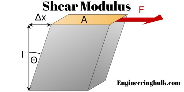
Shear modulus formula, units and sign convention
Take a rectangular block, fix its bottom face and apply a force F tangentially along the top face of area A. The block does not stretch; it leans over into a parallelogram.
- Shear stress τ = F / A, in N/m2 or Pa.
- Shear strain γ = Δx / h = tan θ ≈ θ, where Δx is the sideways movement of the top face and h is the height. For elastic strains the angle is tiny, so the tangent equals the angle. γ is in radians and is dimensionless.
- Shear modulus G = τ / γ = (F/A) / (Δx/h) = F h / (A Δx).
Because γ has no units, G has the same units as stress: Pa, and in practice GPa or N/mm2 (1 GPa = 1000 N/mm2). G is always positive for a stable material, and for every real engineering material G is smaller than Young’s modulus E, usually a little under half of it.
One point that costs marks in exams: γ must be in radians, not degrees. If you measure a distortion of 0.05 degrees, convert it with π/180 before dividing.
How shear modulus differs from Young’s modulus and bulk modulus
The three elastic constants describe three different ways of deforming the same material.
| Constant | Loading | Definition | What changes | Steel value |
|---|---|---|---|---|
| Young’s modulus E | Direct tension or compression along one axis | E = σ / ε (normal stress over normal strain) | Length changes, and the volume changes too | ≈ 200 GPa |
| Shear modulus G | Tangential force along a face | G = τ / γ (shear stress over shear angle) | Shape changes, volume stays the same | ≈ 79 GPa |
| Bulk modulus K | Uniform pressure on all faces | K = −p / (ΔV/V) | Volume changes, shape stays the same | ≈ 160 GPa |
Poisson’s ratio ν is the fourth member of the set, the ratio of lateral contraction to axial extension. For an isotropic material only two of these four are independent: fix any two and the other two follow.
Relations between the elastic constants
The three standard relations, all for isotropic linear-elastic materials:
- E = 2G(1 + ν), so G = E / [2(1 + ν)]
- E = 3K(1 − 2ν), so K = E / [3(1 − 2ν)]
- E = 9KG / (3K + G)
Where the first one comes from, briefly. A state of pure shear τ is equivalent to a tension τ acting on one 45° diagonal plane and an equal compression τ on the perpendicular diagonal. Writing the direct strain along the tensile diagonal under that two-dimensional stress state gives ε = (τ/E)(1 + ν). Geometry of the distorted square says the diagonal strain is half the shear strain, ε = γ/2. Setting the two equal gives γ/2 = (τ/E)(1 + ν), and since G = τ/γ, this rearranges to E = 2G(1 + ν). The second relation comes the same way, from a hydrostatic stress state where each of the three direct strains is (p/E)(1 − 2ν). Eliminating ν between the first two gives the third.
These relations also fence in Poisson’s ratio. For G and K to stay positive, ν must lie between −1 and 0.5. Metals sit near 0.27 to 0.33, so G falls near 0.38E. Rubber has ν very close to 0.5, which is why it barely changes volume and why its K is thousands of times its G.
Worked example: finding G and K for steel
Given E = 200 GPa and ν = 0.30 for mild steel:
- G = E / [2(1 + ν)] = 200 / (2 × 1.30) = 200 / 2.60 = 76.9 GPa
- K = E / [3(1 − 2ν)] = 200 / (3 × 0.40) = 200 / 1.20 = 166.7 GPa
- Check with the third relation: E = 9KG/(3K + G) = 9 × 166.7 × 76.9 / (500.1 + 76.9) = 115,373 / 577.0 = 200.0 GPa. Consistent.
Measured G for structural steels is usually quoted as 77 to 80 GPa, so a calculated 76.9 GPa from E = 200 GPa and ν = 0.30 lines up well.
Typical shear modulus values
| Material | Shear modulus G (GPa) | Note |
|---|---|---|
| Carbon / structural steel | 79 to 80 | The standard design value is 79.3 GPa; spring design normally uses 79 to 81 GPa. |
| Stainless steel | 75 to 77 | Slightly lower than carbon steel. |
| Grey cast iron | 40 to 50 | Varies strongly with grade and graphite form; 41 GPa is the value most tables quote for a common grade. |
| Copper | 45 | Annealed, room temperature. |
| Brass | 40 | Composition dependent. |
| Aluminium and its alloys | 25 to 26 | About one third of steel, which is why an aluminium shaft twists three times as much for the same torque and section. |
| Titanium alloy | 44 to 45 | Ti-6Al-4V. |
| Glass | 26 to 32 | Borosilicate near 32, Pyrex near 26.5, ordinary float glass near 30. |
| Concrete | 10 to 21 | Published values disagree. Computing it from E = 25 to 30 GPa and ν = 0.20 gives about 10 to 12 GPa, while some tables print 21 GPa. Always state which E and ν you used. |
| Rubber | 0.0003 to 0.001 | 0.3 to 1 MPa. Roughly a hundred thousand times less rigid than steel. |
Values for metals are approximate and shift a few per cent with alloy, heat treatment and temperature. Take a design value from the material standard, not from a general table.
Application 1: torsion of a shaft
This is where shear modulus earns its keep. For a circular shaft carrying pure torsion, the torsion equation is:
T / J = τ / r = Gθ / L
with T the torque in N·m, J the polar second moment of area in m4, τ the shear stress at radius r in Pa, θ the angle of twist in radians and L the shaft length in m. For a solid circular shaft J = πd4/32, and for a hollow shaft J = π(do4 − di4)/32.
Two results fall straight out:
- Maximum shear stress τmax = T rmax / J, at the outer surface. G does not appear, so strength is not a function of G.
- Angle of twist θ = T L / (G J). Here G decides everything. GJ is the torsional rigidity of the section.
Worked example: angle of twist of a solid steel shaft
A solid steel shaft 50 mm in diameter and 1.5 m long carries a torque of 1200 N·m. Take G = 79 GPa. Find the angle of twist and the maximum shear stress.
- Polar second moment of area. J = πd4/32 = π × (0.050)4 / 32 = π × 6.25 × 10⁻⁶ / 32 = 6.136 × 10⁻⁷ m4
- Torsional rigidity. GJ = 79 × 109 × 6.136 × 10−7 = 48,474 N·m2
- Angle of twist. θ = TL / (GJ) = (1200 × 1.5) / 48,474 = 1800 / 48,474 = 0.0371 rad
- In degrees: 0.0371 × 180/π = 2.13°
- Maximum shear stress. τmax = T r / J = (1200 × 0.025) / (6.136 × 10⁻⁷) = 30 / (6.136 × 10⁻⁷) = 4.89 × 10⁷ Pa = 48.9 MPa
Both results are comfortable for a mild steel shaft. A common design limit for a transmission shaft is about 0.25 to 1 degree of twist per metre of length; here 2.13° over 1.5 m is 1.42° per metre, so on a precision drive you would go up a size even though the stress is low. Stiffness, not strength, sets the diameter in many shafts.
Swap the material for aluminium at G = 26 GPa and nothing about the stress changes, but the twist becomes 0.0371 × 79/26 = 0.113 rad, which is 6.46°. Three times the twist, same stress. That comparison is the cleanest demonstration of what G actually controls.
Application 2: helical springs
A close-coiled helical compression spring under an axial load does not bend; the wire is loaded almost entirely in torsion. So the spring constant depends on G, never on E:
k = G d4 / (8 D3 n)
where d is the wire diameter, D the mean coil diameter, n the number of active coils and k the stiffness in N/m. Note the fourth power on d: increase the wire diameter by 10 per cent and the spring gets about 46 per cent stiffer.
Worked example: stiffness of a compression spring
Spring steel wire d = 5 mm, mean coil diameter D = 40 mm, 10 active coils, G = 79 GPa.
- d4 = (0.005)4 = 6.25 × 10⁻¹⁰ m4
- D3 = (0.040)3 = 6.40 × 10⁻⁵ m3
- Numerator: G d4 = 79 × 109 × 6.25 × 10−10 = 49.375 N·m2
- Denominator: 8 D3 n = 8 × 6.40 × 10−5 × 10 = 5.12 × 10⁻³ m3
- k = 49.375 / 5.12 × 10−3 = 9644 N/m = 9.64 N/mm
- Deflection under a 100 N load: δ = F/k = 100 / 9644 = 0.0104 m = 10.4 mm
Application 3: shear in beams, fasteners and pins
A bolt, rivet or pin carrying a transverse load is in direct shear. In single shear there is one failure plane and τ = F/A. In double shear, where the pin passes through a clevis and is cut by two planes, τ = F/2A, so the same pin carries twice the load. G does not set the failure load here, since that comes from the shear strength of the material, but G controls the elastic slip and the joint’s stiffness before slip.
In beams, transverse shear produces a parabolic shear stress distribution across a rectangular section with a maximum of τmax = 1.5 V/A at the neutral axis. The additional deflection this causes is inversely proportional to G. For a slender beam the shear deflection is negligible next to the bending deflection, but for deep or short beams, sandwich panels and composite laminates, where G is low compared with E, it becomes a real part of the answer.
How shear modulus is measured
The standard laboratory method is a torsion test. A circular specimen of known diameter and gauge length is gripped at both ends and twisted while a torsiometer records the angle of twist against applied torque. In the straight, elastic part of the torque versus twist plot, the slope gives G directly:
G = (T / θ) × (L / J)
ASTM E143 is the standard test method for shear modulus at room temperature and specifies the specimen geometry and the range over which the slope should be taken. Two practical points: use the elastic portion only, well before the torque curve bends over, and take the twist from a gauge length on the specimen rather than from the machine head, because grip slip and machine compliance inflate the measured angle and give a G that is too low.
G can also be obtained without breaking anything, using a dynamic or ultrasonic method. Measure the shear wave velocity vs through the material and use G = ρvs2, with ρ the density. Dynamic values usually come out a per cent or two higher than static torsion values.
How temperature affects shear modulus
G falls as temperature rises, because thermal expansion increases the average atomic spacing and weakens the interatomic bonding that resists distortion. The drop is gentle over normal service temperatures and steep once the material approaches a transition.
- Steel: the elastic moduli fall slowly to about 200°C, then faster. Eurocode 3 Part 1-2 gives the retained fraction of the elastic modulus of structural steel as roughly 0.70 at 400°C, 0.60 at 500°C and 0.31 at 600°C, and G follows the same trend. That is why fire design of steel structures is a stiffness problem as much as a strength one.
- Aluminium: loses stiffness earlier than steel because its melting point is lower.
- Polymers and rubber: the change is dramatic. Below the glass transition temperature a polymer is a stiff glass with G in the GPa range; above it the same material is rubbery with G in the MPa range, a fall of three orders of magnitude over a narrow temperature band. This is why an engine mount or a suspension bush behaves quite differently at 5°C in a Delhi winter and at 45°C in May.
For any design that runs hot, take G at the working temperature rather than the room-temperature table value.
References
- NPTEL, Strength of Materials, IIT lecture series on elastic constants and torsion.
- Shear stress, background reading.
- AICTE Model Curriculum, Mechanics of Solids.
- ASTM E143, Standard Test Method for Shear Modulus at Room Temperature.
- EN 1993-1-2 (Eurocode 3 Part 1-2), reduction factors for the elastic modulus of structural steel at elevated temperature.
FAQs
What is shear modulus and what is its formula?
Shear modulus, or modulus of rigidity G, is the ratio of shear stress to shear strain within the elastic limit: G = τ/γ = (F/A)/(Δx/h). Shear strain γ is the angle of distortion measured in radians, so it is dimensionless and G has the units of stress, normally GPa. It measures resistance to a change of shape at constant volume.
What is the shear modulus of steel?
About 79 GPa for carbon and structural steel, commonly quoted as 79.3 GPa, and 75 to 77 GPa for stainless steel. It can be checked from E = 2G(1 + ν): with E = 200 GPa and ν = 0.30 the calculation gives G = 200/2.6 = 76.9 GPa, close to the measured value.
What is the relation between E, G, K and Poisson’s ratio?
For isotropic materials E = 2G(1 + ν), E = 3K(1 − 2ν) and E = 9KG/(3K + G). Only two of the four constants are independent, so fixing any two determines the rest. The first relation comes from treating pure shear as equal tension and compression on the two 45 degree diagonal planes.
How do you calculate the angle of twist using shear modulus?
Use θ = TL/(GJ) from the torsion equation T/J = τ/r = Gθ/L. For a solid steel shaft of 50 mm diameter and 1.5 m length carrying 1200 N·m with G = 79 GPa: J = πd4/32 = 6.136 × 10⁻⁷ m4, GJ = 48,474 N·m2, so θ = 1800/48,474 = 0.0371 rad, which is 2.13 degrees.
Is shear modulus the same as shear stiffness?
No. Shear modulus is a material property in pascals and is independent of size. Shear stiffness belongs to a specific component and depends on geometry as well: torsional rigidity is GJ, and a helical spring’s stiffness is k = Gd4/(8D3n). The same steel gives very different stiffness in different shapes.